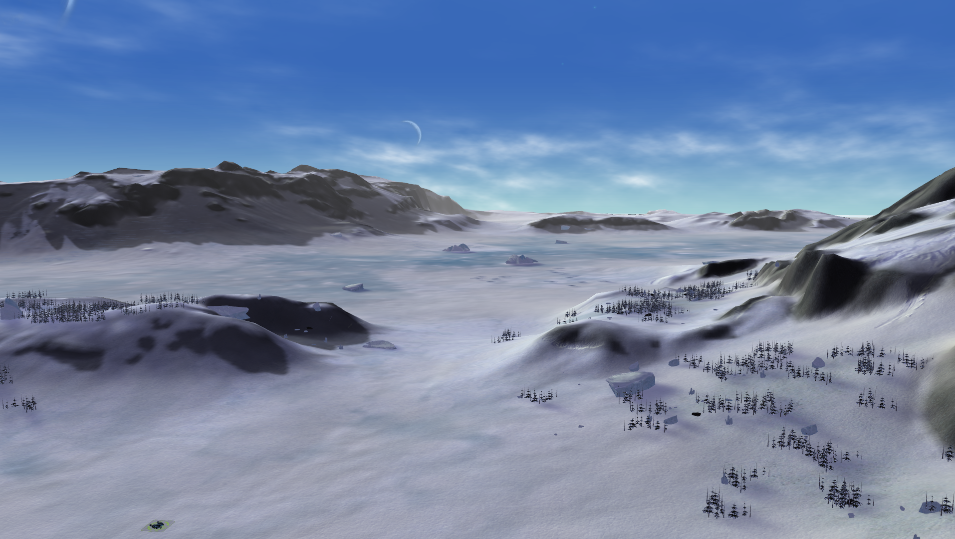
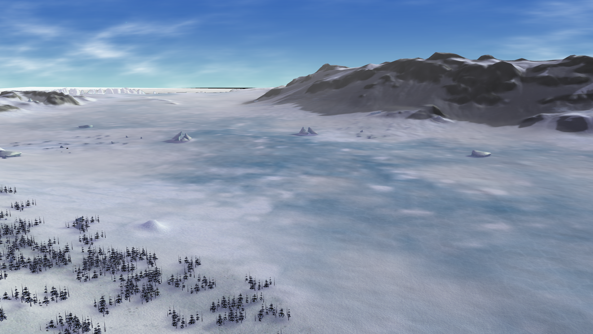
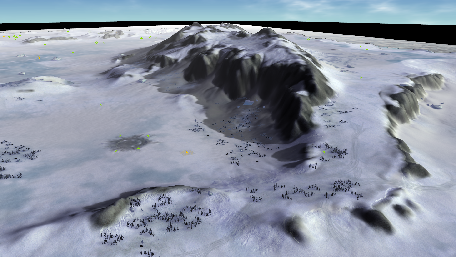
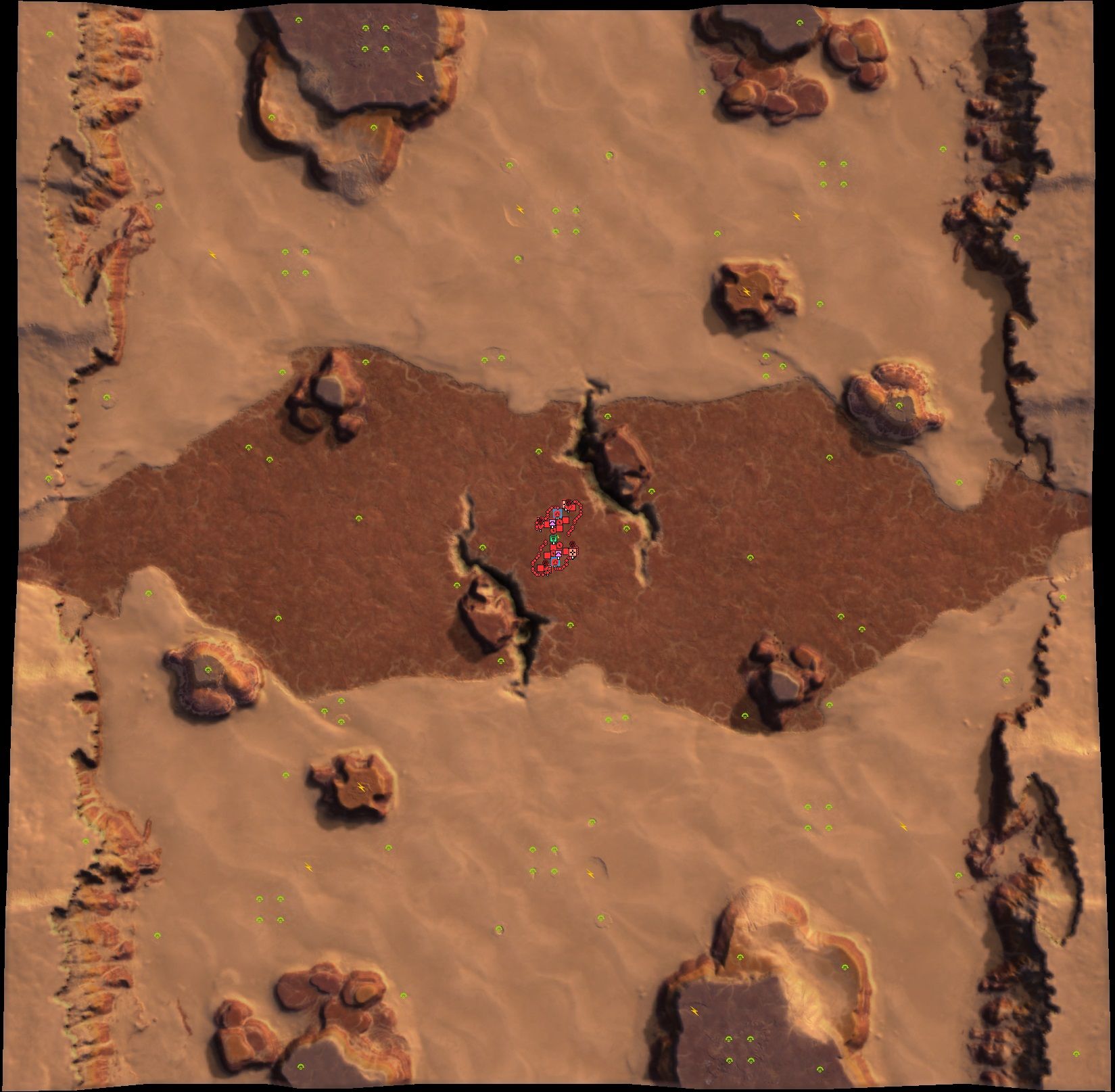
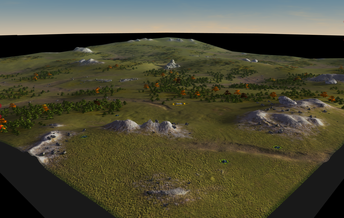
Gaea tutorial: A basic introduction to mapping with Gaea
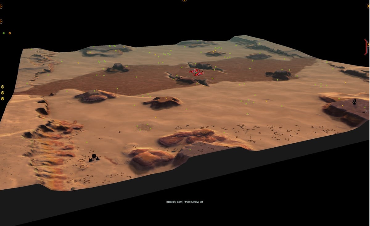
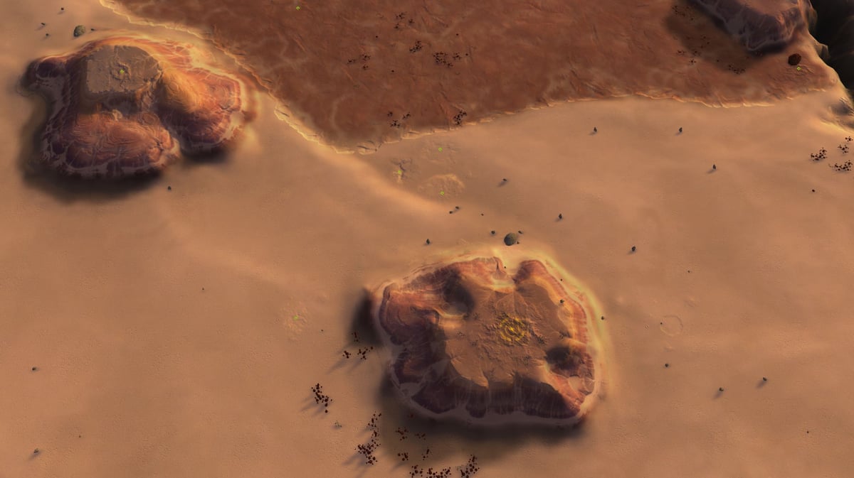
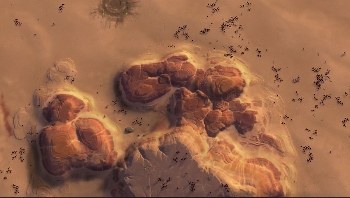
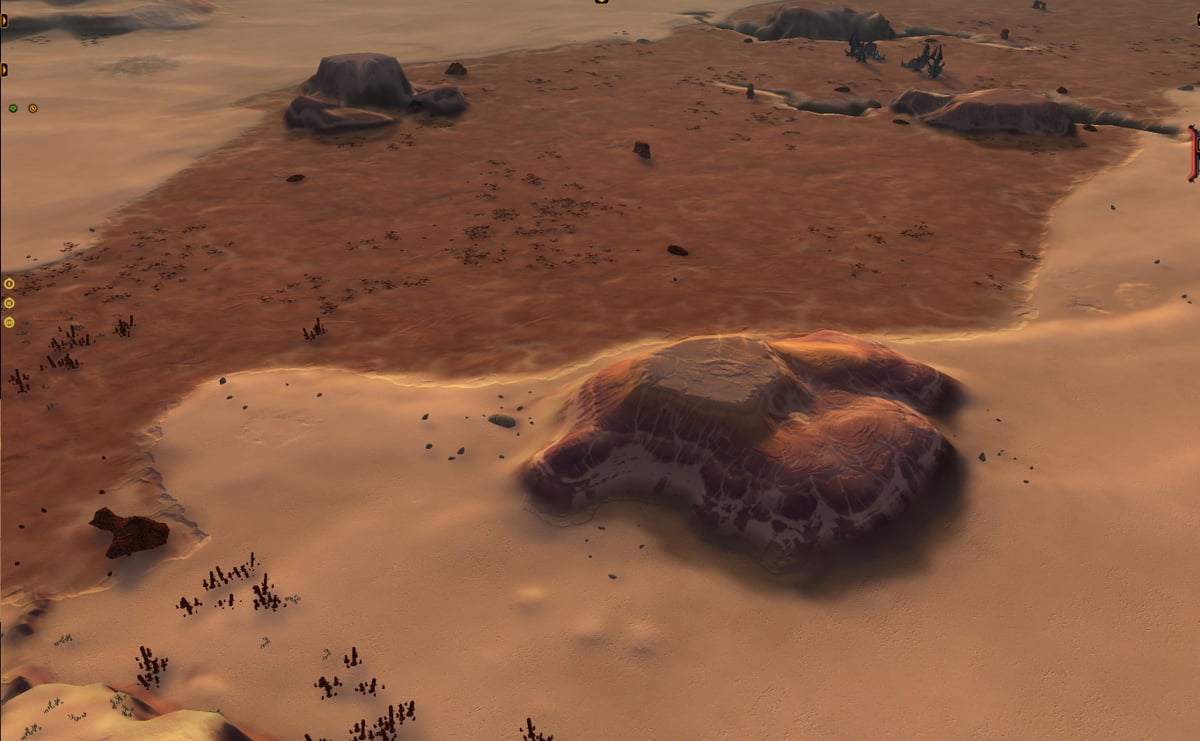
The various map projects I've made have all been made possible by Quadspinner's Gaea, a terrain design application for VFX and games. Gaea is an industry standard and a great tool to significantly speed up creating or increasing the complexity of masks, heightmaps, and decals. Because of FAF's peculiarities and the fact that the game is more than a decade old, the process of producing these assets using Gaea is a bit involved. Being the shiny beacon of enlightenment that I am, in this tutorial series I will explain my process for creating all the relevant map assets in gaea (see figure 1). This specific tutorial will discuss the basics of Gaea and how it can be used to create the main heightmap for your terrain.
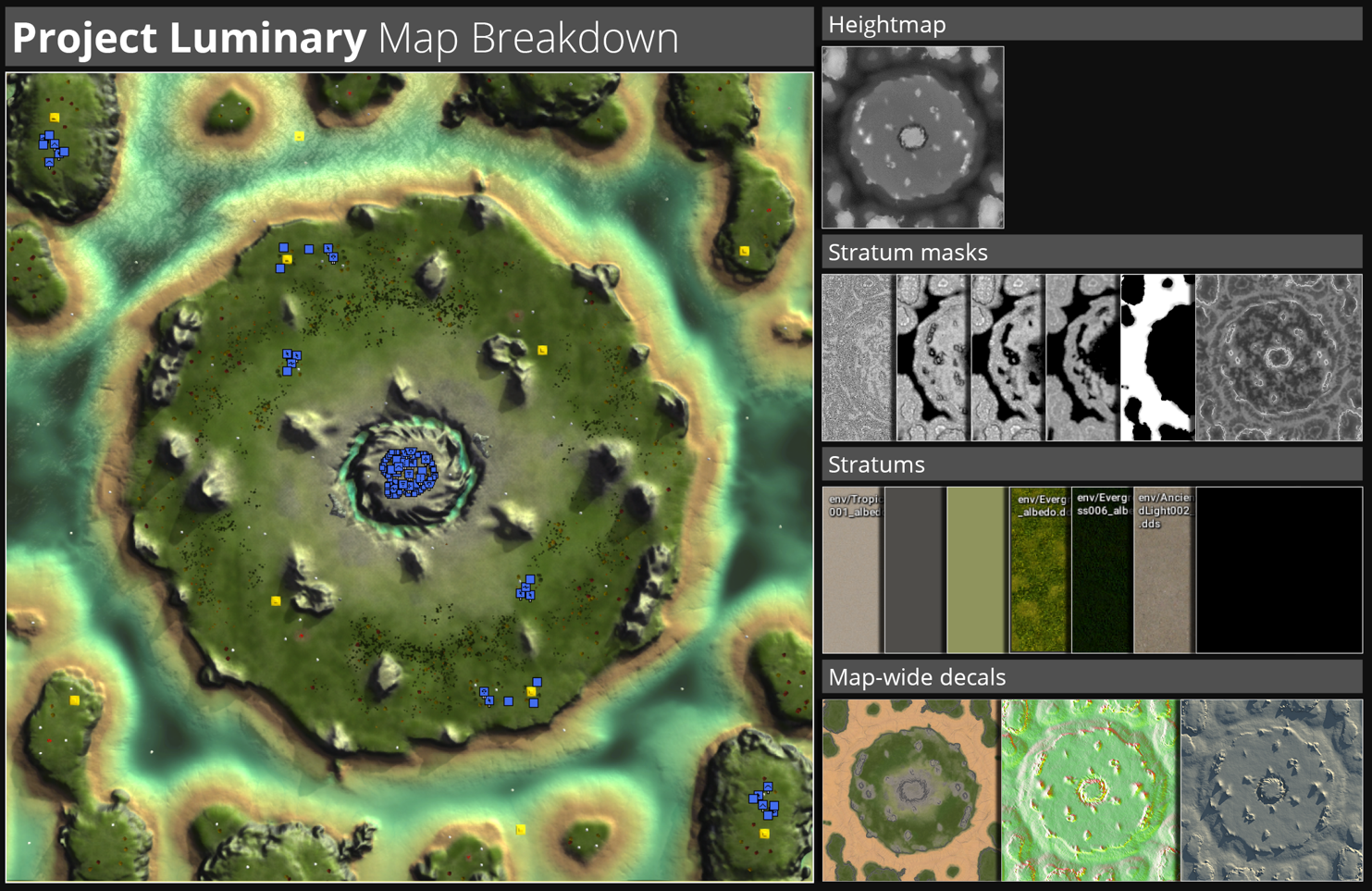
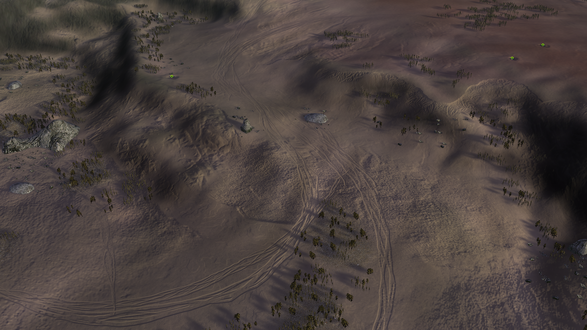
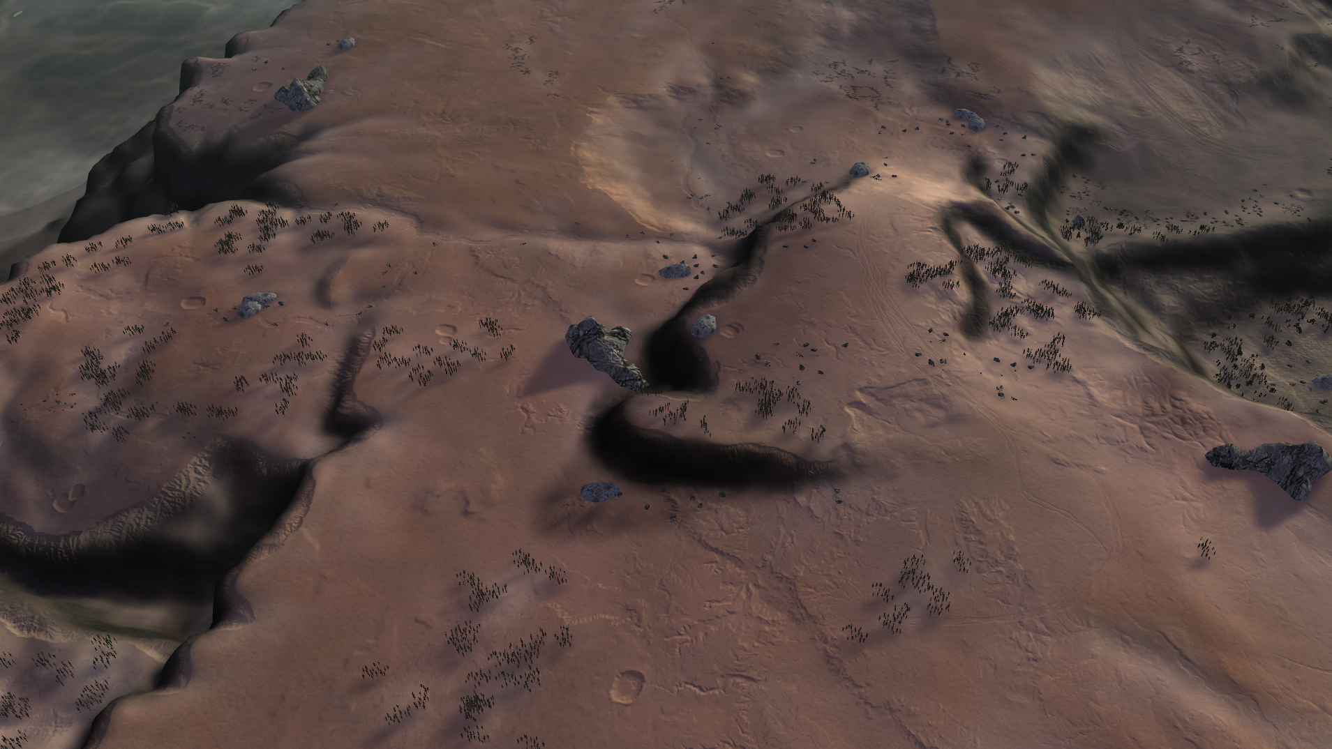
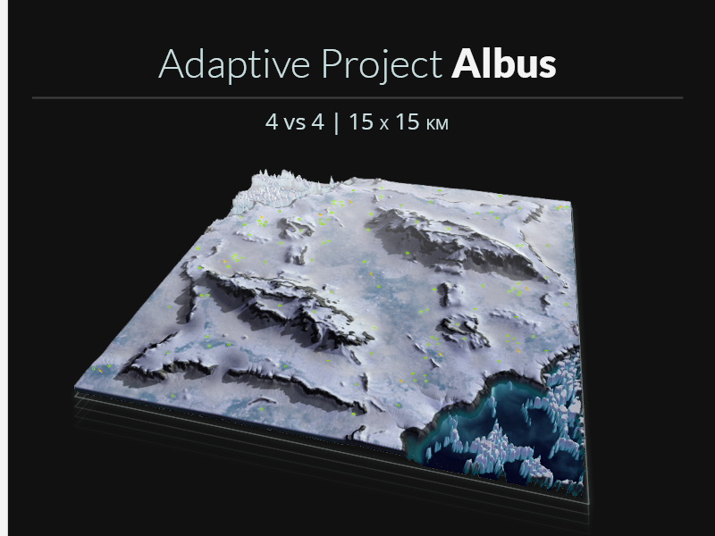
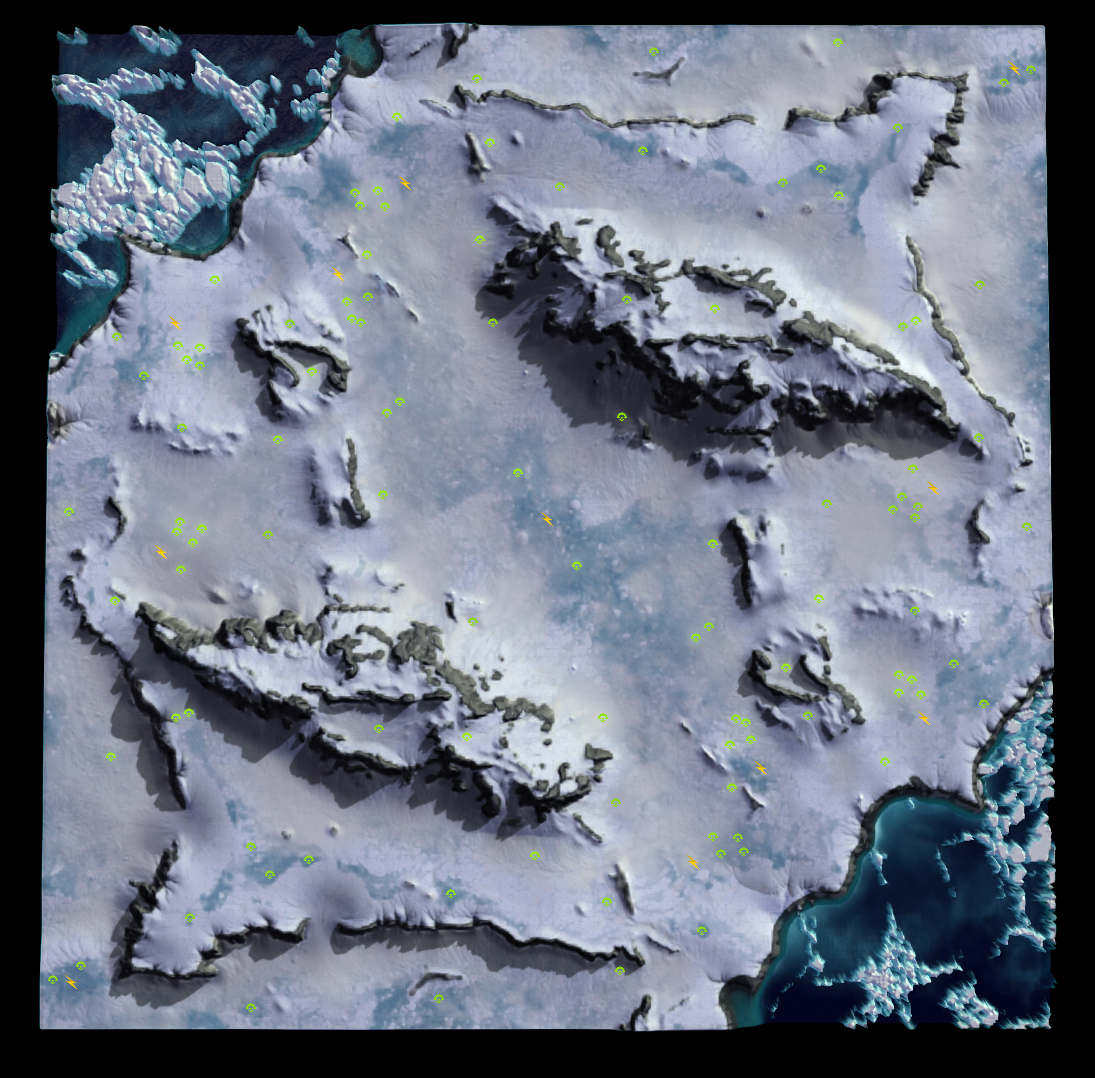
Figure 1: a breakdown of the map Project Luminary to show all the assets generated in Gaea. Note: some of the stratum textures are stock-FAF textures and were not created in Gaea, but are here included to illustrate the different components of the map.
Prerequisites
This tutorial assumes you've got a basic understanding of image editing and FAF mapping. Additionally, while this specific tutorial will explain some of the basics of visual node based programming, the technique Gaea uses to create the assets, it is recommended that you take some time to familiarize yourself with the concept and Gaea in particular. This 6-minute video is highly recommended, as is giving the general documentation for gaea a read. Using this node system may look daunting at first, but is very intuitive and easy to learn.
Required tools
Required for this tutorial is a copy of Gaea (the indie version is free to use and more than sufficient for maps up to 20km), which can be downloaded here. Additionally, an image editor such as Photoshop or Gimp is required, though the free to use online photoshop-clone Photopea works fine too. Finally, you need to have installed the FAF map editor.
Footnotes marked as '[0]' where needed. Notes are added to the bottom of the tutorial.
When specific nodes are referenced, they are highlighted like this: Node. Specific parameters for these nodes are written like this: Slope, 30, 90, 0, to specify a Slope node with Parameters 30 (min), 90 (Max), and 0 (Falloff).
Introducing Gaea
Gaea is a graph-based application for creating terrain and focussed on providing techniques to simulate realistic erosion. To create these terrains, different nodes are linked to eachother. Nodes affect or combine with other nodes to create complex shapes and structures. While working in Gaea, you will navigate between several panels.
The workspace
As of June 2023, a typical workspace in Gaea might look like Figure 2. The workspace can be configured to your preferences, with different panels moved or scaled. The largest part of the screen is taken up by the viewports and the graph surface. The viewport shows you the terrain and masks, the view of which can be rotated, scaled, and panned. Optionally, you can press the 2D button in the viewport toolbar to show the second, top-down, viewport. Below the viewports, you will see the graph surface, where your nodes and their connections are displayed. Clicking on a node will show the contents of that node in the viewports.
! Tip: you can lock the viewport to show one specific node by selecting the node and pressing F on the keyboard. The node will be marked with a small green circle on the bottom right of the node to indicate the viewport is locked on that node. This is very useful when you are adjusting parameters of nodes earlier in the chain, but want to see the result on a specific node later in the chain. Press F again while selecting the node to unlock the viewport.
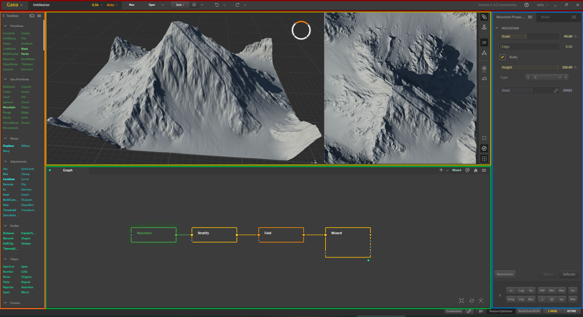
Figure 2: Typical workspace of Gaea. Colored accents added to highlight the different panels. Red: Main toolbar. Orange: Toolkit containing various nodes. Yellow: Viewport, 2D viewport, and viewport toolbar. Green: Graph surface. Blue: Properties panel.
The toolbox contains all the nodes you can put onto the graph surface. Nodes are grouped by type, and have a specific colour to signify which group they belong to.
Clicking on a node will also reveal the properties panel for that node. Here, you can adjust the effect or contents of the specific node.
Above all the other panels is the main toolbar, which contains a few important things to discuss. First, the viewport resolution can be selected in this panel. It is generally recommended to select the resolution that you will be exporting your heightmap in. Gaea recalculates the terrain and parameters of the nodes every time you switch resolution, and the resolution can drastically affect how the terrain is shaped. Aside from the obvious increase in fine details, you might find that elements have changed shapes or moved when comparing different resolutions.
! As the terrain changes based on the resolution it is rendered in, creating high-resolution map-wide decals might result in some mismatch between the heightmap and the decals. A method to prevent this will be discussed in the tutorial on map-wide assets.
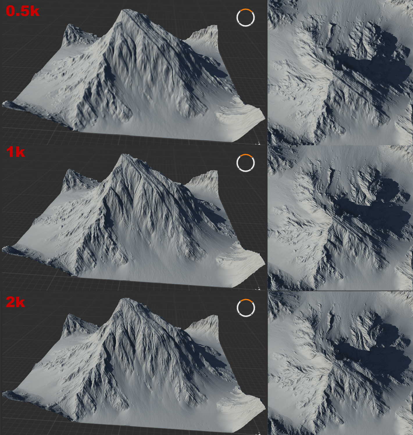
Figure 3: Showing the differences between the viewport at 0.5k, 1k, and 2k resolution. Note the increase in fine details.
Another important section of the main toolbar is the save button. Attached to the save button is a smaller button labeled with (+). This button will create a version-copy of your project: if a project is named 'Project Luminary V1', clicking this button will create a new savefile labelled "Project Luminary V1001". The next time you click the button, the new savefile will be labelled "Project Luminary V1002". I cannot stress enough how important it is to regularly create a new version. Since before I started using Gaea, the undo and redo buttons have been rather dysfunctional. Maintaining a recent version of your project will ensure you do not lose large sections of your work when you inevitably have to undo changes that the undo-button refuses to process. Note that the save-files Gaea creates are very small: do not hesitate to create new savefiles.
Nodes and graphs
As mentioned, nodes are sorted by type and colored accordingly. Generally, basic nodes that create a type of terrain are green. Nodes that transform or adjust other nodes are generally light blue or teal. Nodes that apply erosion or aggressively 'damage' terrain are light or dark orange. A different, darker shade of orange is reserved for Data nodes, which are nodes that can be used to mask or select parts of the terrain based on certain parameters. When creating textures, the purple nodes will allow you to work with colour.
Nodes often have one or more inputs, and one or more outputs. A Combine node, for example has three inputs and two outputs. Hovering over the little dot marking the node's in- or output will show the name of the port and indicate whether or not a connection is required for the node to function. Ports that need a connection have the same colour as the node-type, while optional ports are grey. Additionally, many ports have a designated input for masks. Adding a node (A) to the mask-input of another node (B) allows you to restrict the effect of node (B) to the specific area determined by node (A). Connections to a mask-input are always coloured purple, to indicate the type of connection.
Nodes that are improperly connected will have a red-dotted border and display the text "error". A node that has not been rendered yet will show as a blue-dotted bordered node. Clicking on this node (and, if required, un-locking any previously locked nodes from the viewport) will prompt Gaea to calculate the effect of the node and display its contents. Nodes that are selected will be marked with a blue glow. The node will then turn into a solid-bordered node, or if failed, be marked with an error.
! Sometimes, Gaea runs into an error that it refuses to get unstuck from. In most cases, it suffices to select the whole graph and press the 'Force a Refresh' button at the right bottom corner of the graph surface. If this does not resolve the issue, double check your connections (a common mistake is to connect to a secondary input rather than a primary input) or restart Gaea.
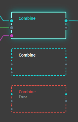
Figure 4: A properly connected and selected node, an unrendered node, and a node that was rendered but produced an error. Note how the first node has three inputs, one of which is a mask, and one output.
Node parameters
Each node has a particular set of parameters that can be adjusted to change the result of the node. Some of these have obvious effects: the Height parameter for the Constant node affects the height of the flat plane that the node generates. Common parameters include Scale and Seed. Seed in particular is a very powerful parameter common to nearly all nodes: changing the seed value randomizes the noise used to generate the effect of the node, which changes the outcome significantly (see figure 5). Other parameters are less intuitive, and require some experimenting to understand how the node is affected.
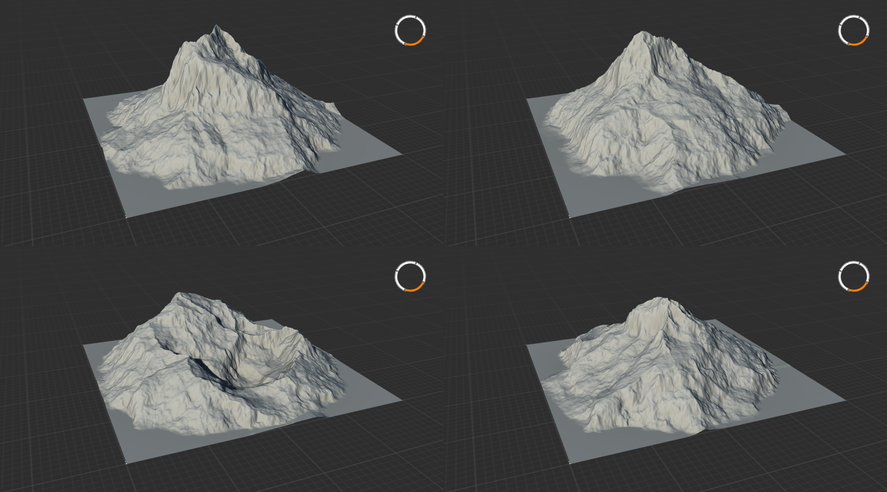
Figure 5: Four copies of a mountain node with identical settings but different seeds.
Creating a heightmap for FAF
Creating your first terrain
Primitives
Whether you have a design in mind or are hoping to combine nodes until something presentable falls out, you're going to want to start out with one of the primitives. This category of node is coloured green and serves as the basic building blocks for your terrain. Half of this category consists of 'plain' primitives: the Constant node produces a flat plane, the Gradient node produces a ramp or a cone. Different types of noise generators are included as well, such as Gabor, LineNoise, Voronoi, and Multifractal.
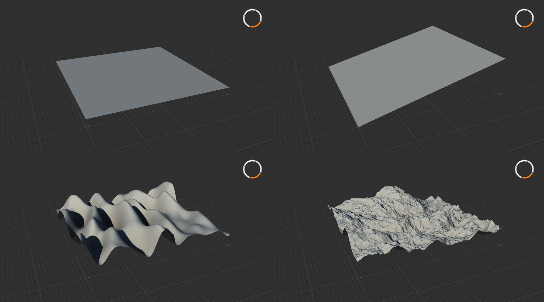
Figure 6: A selection of primitive nodes: Constant, Gradient, Gabor, and MultiFractal.
Geo primitives
The other half of this categories includes more complex presets of common terrain features. Among these Geo Primitives you will find nodes such as Badlands, Crater, Mountain, Canyon, Dunes, and Island (figure 7). Many of these advanced nodes can be recreated by combining 'plain' primitives, but as they are rather complex it is often easier to use the Geo primitives.
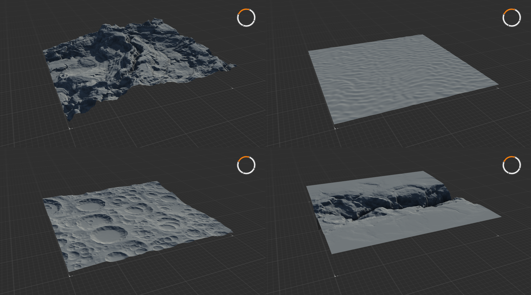
Figure 7: A selection of geoprimitive nodes: Badlands, Dunes, Crater, and Canyon.
Adjustments Nodes
To start adding things together, you'll need some nodes from the next main category: the adjustments nodes. The Combine node does what it says on the tin: you can combine two different nodes into one using different blending modes and strengths. Figure 8 shows the result of blending the Badlands node and Crater node from figure 7 together using four different blendmodes.
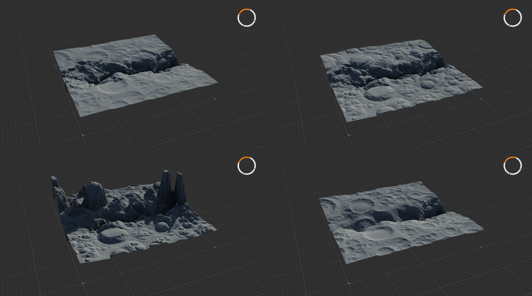
Figure 8: Blending Crater and Badlands using the blending modes Embed, Subtract, Divide, and Insert.
The other be scaled, rotated, and repositioned using the Transform command, while the Clamp node gives you good control over the global height of the terrain.
In my map Project Mesa, for example, I created the basis for the various pillars using a Gradient, Radial node, which I then repositioned and rescaled using the Transform node, and merged with the main terrain using a Combine, Embed node.
Erosion Nodes
Once the basic design of your map has been established, you might want to take a look at the various Erosion nodes. These nodes create rugged looking terrain, simulating decay over time from exposure to the elements. They can be applied to separate elements if you are combining multiple elements into one whole, be limited to specific areas using masks, or can be applied to the whole terrain at once. The Wizard node is a powerful erosion node with many presets that will be adequate in most situations (figure 9).
I want to caution against using Erosion excessively; units in FAF do not like rough terrain: it messes with pathing and blocks shots. While erosion adds lots of detail to a map, consider that the main areas that units fight on should be smooth and relatively flat whenever possible. Naturally, this is of no concern in areas that are limited to air or navy only.
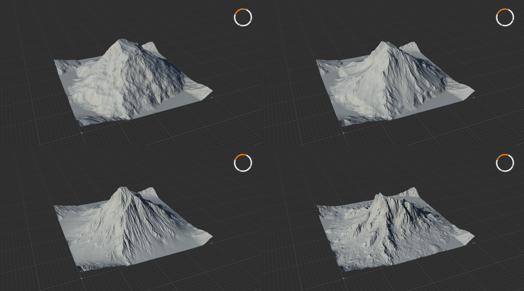
Figure 9: A mountain and three variants with progressively stronger and more aggressive erosion (Wizard) applied. Note the formation of fine details, debris, and lots of sediment.
Modifier parameters
The properties panel of all nodes contains a set of buttons at the bottom right that allow for common modifications to nodes. Several of these modifications have their own nodes with the same effect: the Clmp and Clip buttons imitate the Clamp node, and the Blur button functions as the Blur node.
Aside from these modifications, there are two more settings that are very useful. Be pressing the '>' button, two further options appear. The Influence parameter allows you to reduce the overal effect of the node. The Drop to Floor checkbox lowers the contents of the node to the lowest possible limit, which can be very useful after combining several layers together.
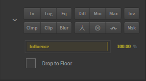
Figure 10: This panel containing modifier parameters is present on all nodes and allows for adjustments without having to add more nodes. The Drop to Floor checkbox is not visible by default and will only show up when pressing the chevron to the left of the buttons.
Using nodes as masks
Using greyscale values to create terrain
So far, we've discussed how nodes can be used to create the terrain for your map. To understand how nodes can also be used to create masks to select specific parts of the terrain, we need to quickly discuss what it is these nodes are creating.
In games such as FAF, a greyscale image creates the terrain. Every pixel of the image has a greyscale value, which ranges from 0, complete black, to 256, complete white. The value of each pixel corresponds to the height of that pixel when it is used to render the terrain. A full white pixel is at maximum height, while a black pixel is at the minimum height. Any values between 0 and 256 correspond to a height somewhere in between the minimum and the maximum.
Gaea similarly translates greyscale pixels to terrain. By default, the viewport renders the resulting 3D terrain for you, but by changing the display mode we can visualize the flat greyscale image. Right clicking on any node and select Show as, Mask, or by selecting a node and pressing T, will change how the viewport renders that node. You will now see the greyscale pixels for your heightmap.
It might be that the greyscale value is still overlaid on the 3D model, rather than shown as a flat plane. This is because Gaea always shows two layers: the node and the underlay. The underlay is the geometry that Gaea projects the contents of a node on top of. This is generally selected automatically, but similarly to how you can freeze a node into the viewport by pressing F, a node can be chosen to serve as underlay frozen by pressing G. To visualize the greyscale image as on a flat plane, you can create a Constant, 0% height node and select that as underlay.
If the image is dark and you would like more contrast to see the different structures, you may press the Show raw data button and the Enhanced view button on the right side of the view port (figure 11).
Since the greyscale value of each pixel is a number, we can easily make selections based on these values. The Data category of nodes contains a lot of nodes that we need to do such selections. The Height node lets you make selections based on the height of the terrain, which corresponds to the higher greyscale value. Similarly, Slope allows you to make selections of pixels that are at a certain angle, by calculating the relationship of a pixel with its neighbours.
For a more extensive introduction to Data nodes to create masks, please see the Gaea tutorial on Masking.
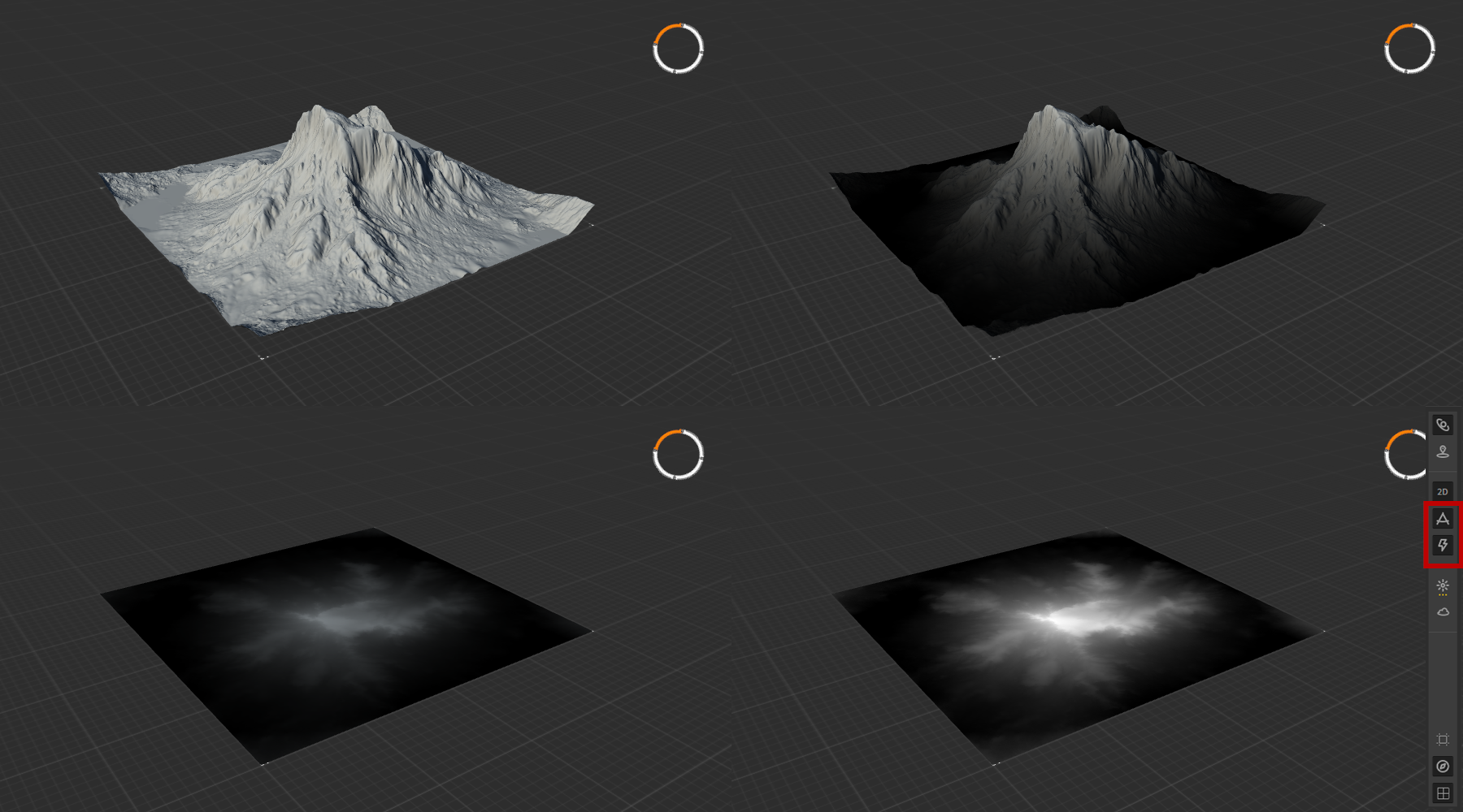
Figure 11: The 3D image, and the corresponding greyscale representation of the raw data for the heightmap. The three greyscale images show the heightmap projected on the 3D model, on a flat plane, and on a flat plane with Enhanced view enabled.
Using greyscale values to select
The greyscale values can also serve to create selections: effects of nodes can be limited to only areas that are white, and not be applied to areas that are black. Greyscale values between white and black correspond to a percentage of the effect being applied. As all nodes contain essentially nothing more than a greyscale image, the outputs of nearly all nodes can be used to make such selections.
By using masks, you get infinitely more control over how nodes are applied. One example might be limiting where erosion is applied. In the fourth panel of figure 10, the erosion is applied to the whole mountain. As an example, we will now limit the erosion to only half of the mountain.
To do this, we first set up our mountain and apply the Wizard erosion node. Then, we create our mask. The mask that we need to limit the erosion to only half of the mountain is a mask that is half white, and half black. Only in the white regions will the erosion effect be applied. To create a full white heightmap, we could take the Constant node and set it to 100% height. Using a Transform node, we could then move the Constant node halfway off of the workspace. As there is no information on the now empty half of the heightmap, these pixels will be black. The results is a heightmap that is white in one half of the image, and black on the other half. When we then use the output of this Transform node and chain it as the mask-input of the Wizard node, we get the result we intend (figure 12).
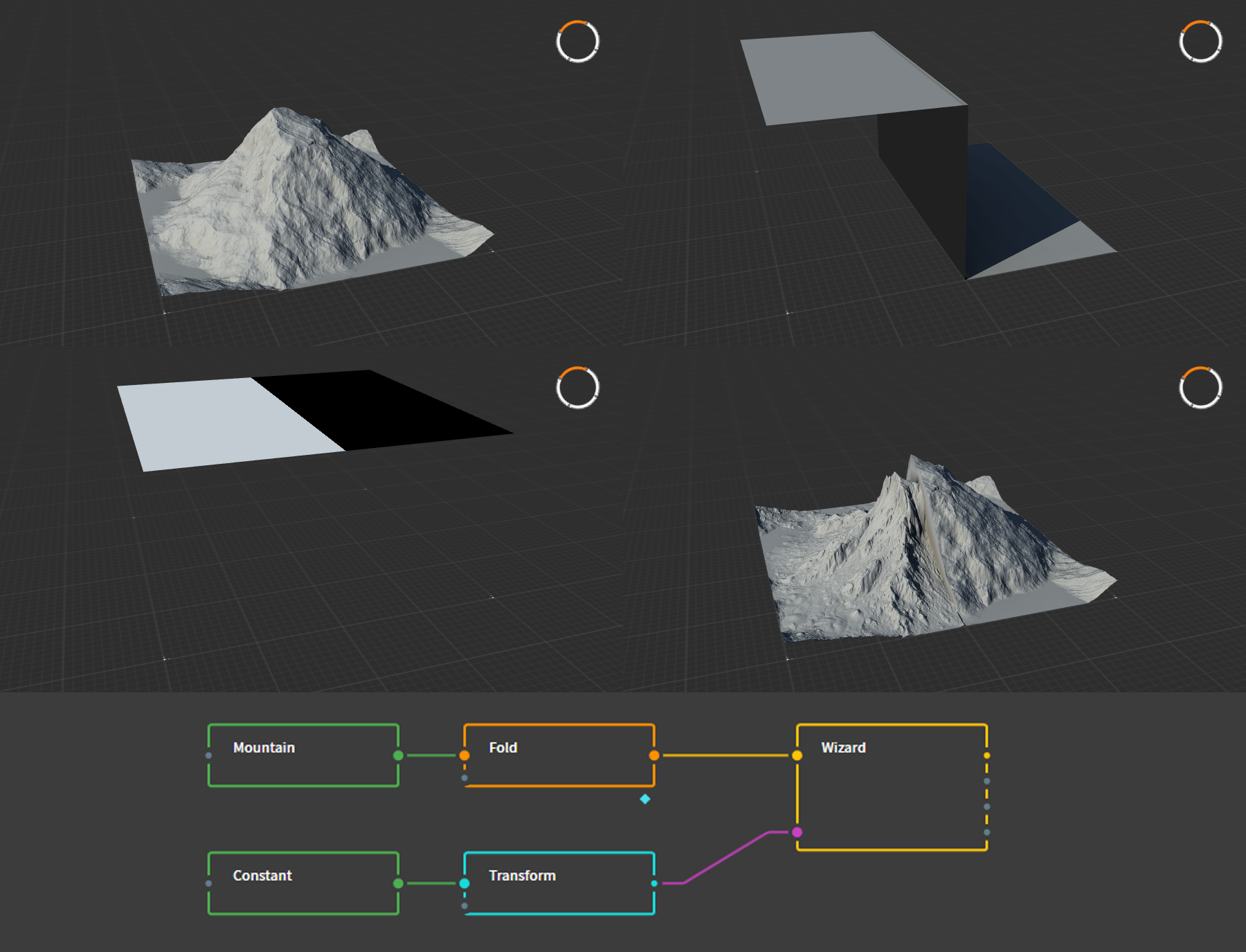
Figure 12: The erosion effect is applied to half of the mountain using a mask. Panel 2 and 3 both show the same node, but the display mode differs. The bottom panel shows the Graph to create this effect. The Fold node shown was used to slightly alter the result of Mountain node, and does not affect the process of making a mask.
Naturally, this specific effect is not something that would work well for a FAF map, but clearly illustrates the principle of using masks.
Other nodes
There are several other useful nodes that you might use to create more advanced materials for your map. These include the Normal Map node, which can be used to create map-wide normal map decals, or the Light node, which can be used to create map-wide shadow decals. As these nodes are more complex, they will be discussed in detail in another tutorial.
Creating symmetry
As Gaea is designed to create realistic and natural terrain, it does not create symmetric terrain by default. In contrast, competitive FAF maps require symmetry to ensure no team has an advantage over the other. Luckily, by combining a few nodes we can create seamless symmetry for all kinds of terrain.
Symmetry of basic terrain
The most simple way to create a symmetric heightmap is done by using the Flip and Combine nodes. The Flip node allows for three different types of mirroring: Horizontal, Vertical, and Both. By combining the flipped copy with the original, you get symmetry.
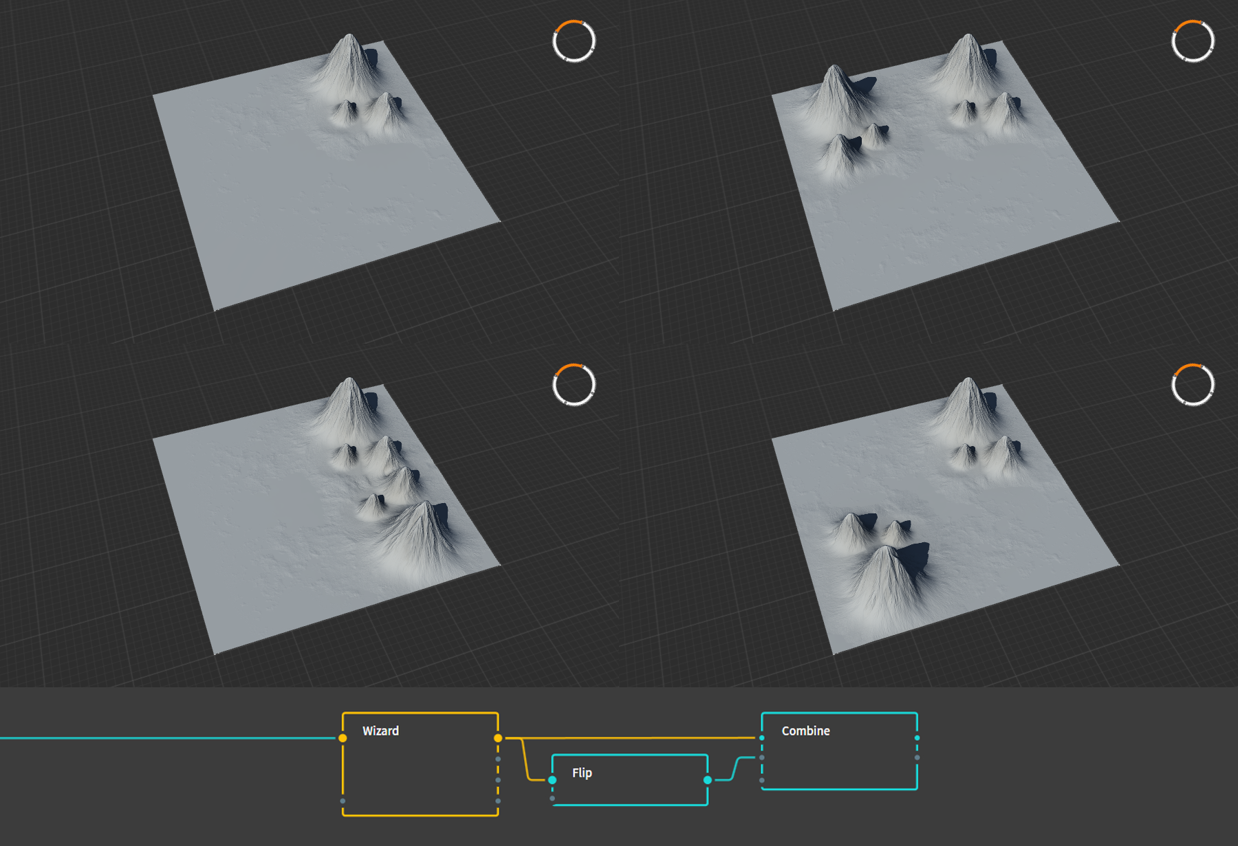
Figure 13: An example of how the Flip node can be used to create three different kinds of symmetry: Horizontal, Vertical, and Both. Combine, Add, 100% was used in these examples.
Rendering your height mask
When you've completed your terrain, you can export it for importing into the FAF editor. To do this, take the last node in your graph and mark that node for export by selecting the node and pressing F3, or by right clicking it and selecting Mark for Export. The marked nodes will now show up under the Build tab in the top right. Adjust the relevant settings:
- Change the filetype of all masks to .raw
- Method should be left on Normal Build
- Resolution should be set to the size corresponding to your map's heightmap (257px for a 5km map, 513px for a 10km map, 1025px for a 20km map).
- Colorspace should be left on sRGB
- Range should be left on Raw, although alternatively this may be set to Remapped to rescale the whole terrain if it proves to be too tall for the FAF editor, see below.
- Baked Cache may be left on Use
After selecting where Gaea should dump the generated files, you can render the files by pressing Start Build.
Rescaling height
If, upon importing the heightmap into the FAF map editor, you realize that there is an issue with the vertical scale, you may want to adjust your heightmap. There are a few easy ways of achieving this. The Clamp node lets you scale the whole heightmap proportionally. Connect this node to the last node of your graph and adjust as necessary. Similarly, under the modifier parameters (those little buttons at the bottom right of a node's parameter panel) you will find the Raise modifier, a circle containing an X. This parameter behaves nearly identical to the Clamp node. Lastly, by setting the Range setting under the build menu to Remapped, and setting the maximum value to some fraction of 1, you can rescale the terrain.
Some trial and error is likely required to find the right scale.
Common errors and checklist
If you are running into problems with importing your heightmap to the FAF editor, please check the following:
- Verify you are using the correct resolution
- Verify you exported the heightmap in the .raw file format.
- Try changing the Baked Cache setting to None and re-render.
If Gaea is producing errors and you cannot get it to work, please check the following:
- Verify that the offending node is properly connected. Remove connections and try again. Nine times out of ten you accidently connected a non-primary output to the next node that cannot use that particular type of data, or connected one node to the a secondary input of the second node.
- Force refresh the complete graph.
- Replace the bugged node.
- Restart Gaea.
If Gaea refuses to render your heightmap, attempt the following:
- Add a
Transform node to the end of the graph, and mark that node for export. Some nodes are known not to produce an output, but the Transform node is known to behave as expected.
Remaining questions
If you are left with questions or need help, your best bet is to check with people in the FAF discord Mapping-General channel. Alternatively, you may send me a PM on discord, or leave a message on this forum.

