Index Librorum's Maps, assorted projects, and Gaea tutorials
-
Version 2
The feedback was processed over the next day: the middle island was increased by 15% and reshaped, and beaches were added across the map. The heightmap was then adjusted by hand using the tools in the FAF editor. I normally prefer to do as much as possible within Gaea, as that makes it a bit easier to create the masks later and I positively suck at hand painting masks and terrain. However, Gaea is really not great at small adjustments in particular places, so hand painting was the way to go. Cliffs were clearly distinguished from slopes, and the original boulders were removed and improved boulders added. Lastly, needlessly bumpy terrain was flattened, which took care of the boring and badly communicated terrain.
Water mexes were placed and another spawn was moved off the main island. During playtesting we noticed that walking the commander from the side island to the main island took no time at all, and having three commanders on the island on the first minute meant it rapidly devolved in a close-combat knife fight, which no one enjoyed. Placing one commander on a side island theoretically solved this very well.
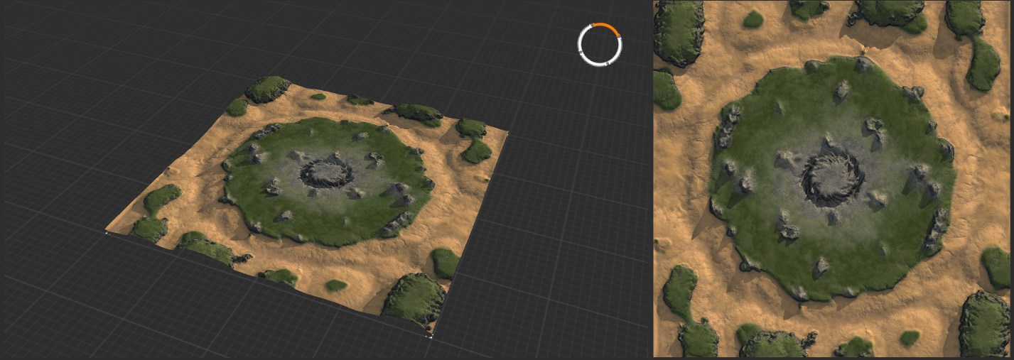
After spending way too long on adjusting some of the textures, a new version for playtesting was slapped together. At this point, a large part of the decal work was completed, trees and other props were added, and the centerpiece was created.
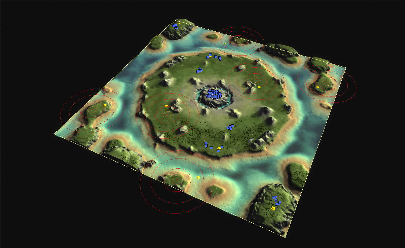
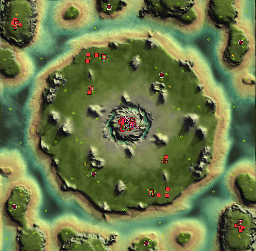
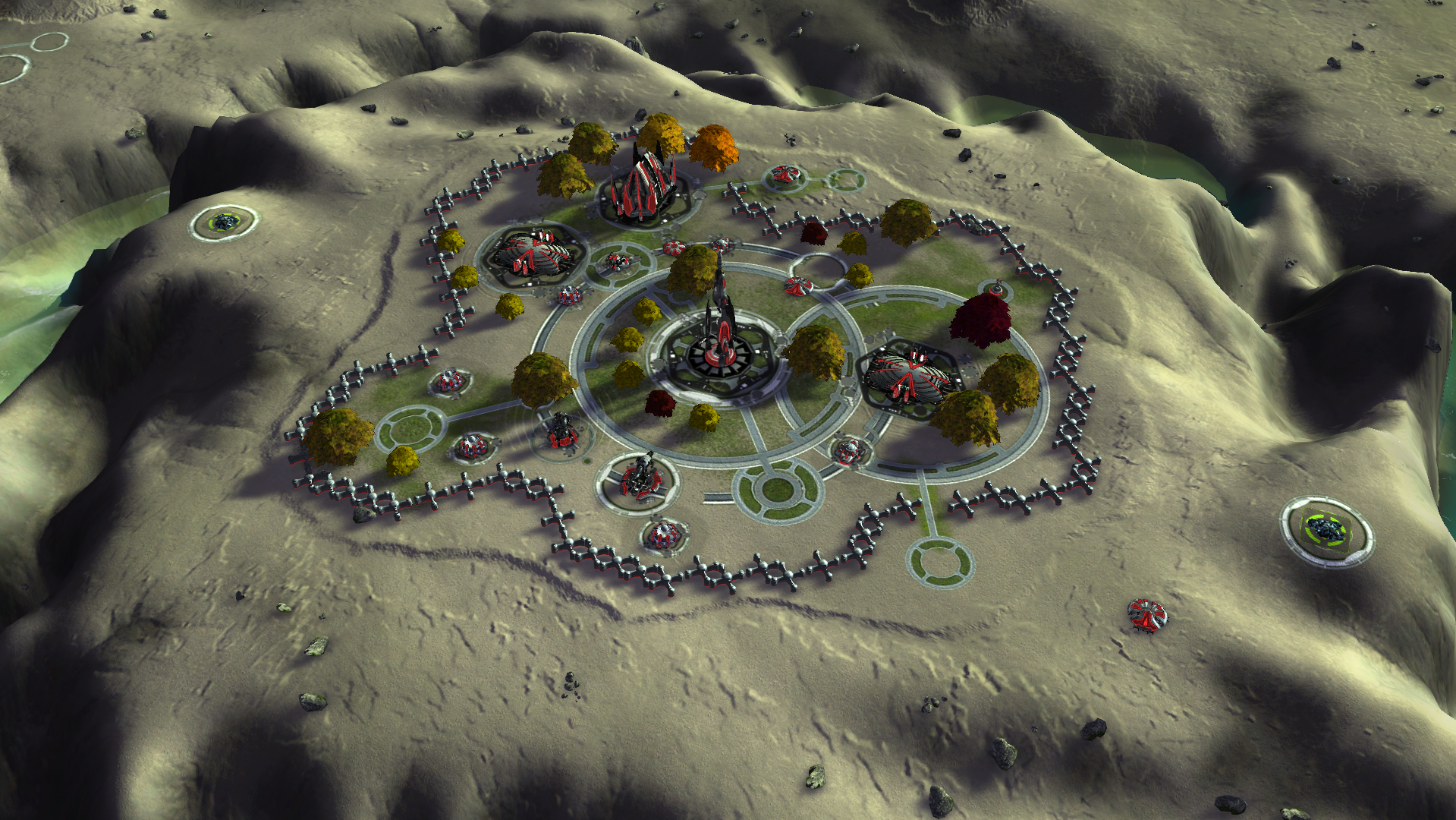
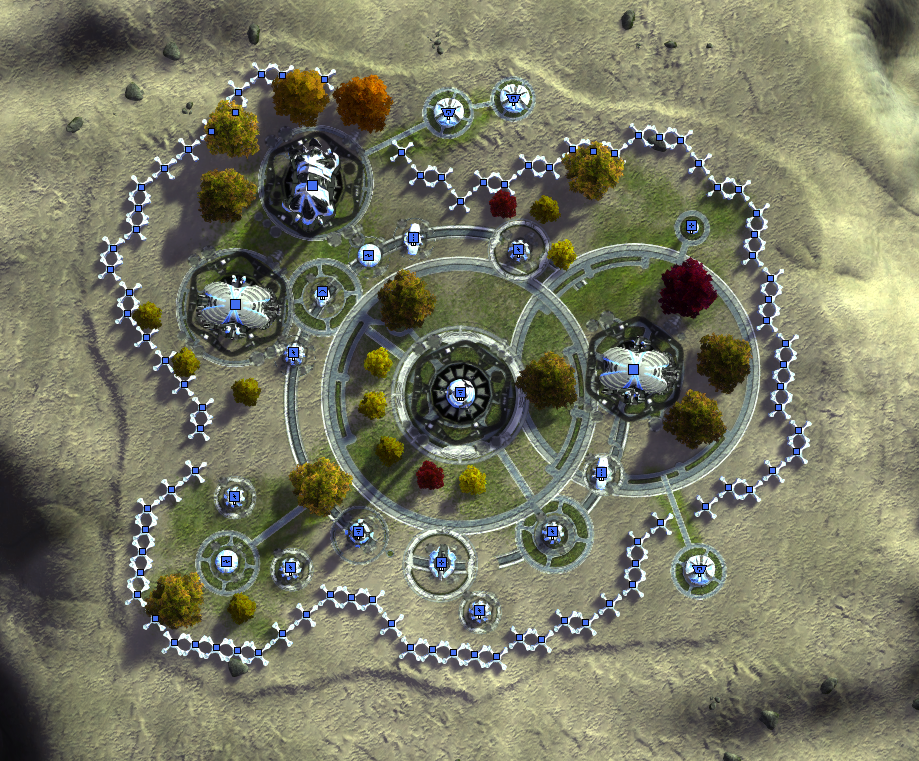
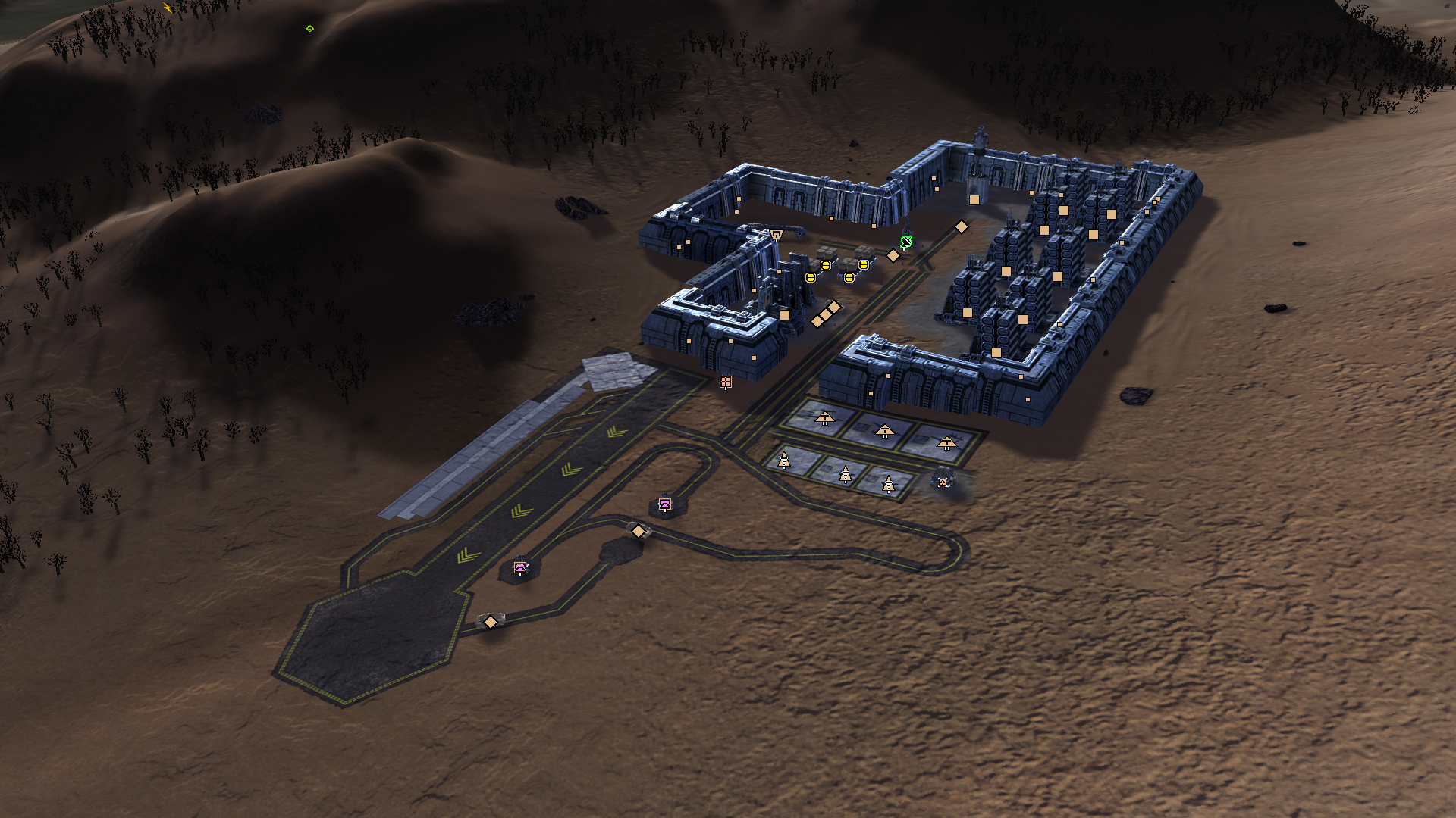
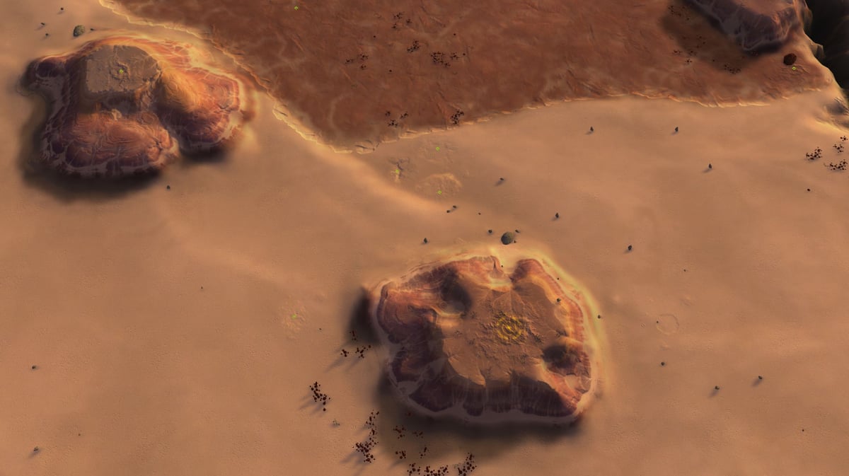
The centerpiece with the heavily fortified Aeon research base was designed with a few purposes in mind. First and foremost, the damn thing just looks really cool and clearly marks the map as an Aeon planet. Lore-wise, the map is designed as the location for the secret research location for the 'Eye of Rhianne', and as such one Eye is placed in the middle of the base. Notice also how precisely the trees are placed: more detail to reinforce the order and symmetry aspects of the map.Secondly, the heavy defenses of the base ensure that no player can quickly claim the middle of the map. With small maps such as these, controlling a center position has a lot of tactical benefits: AA will block a significant and the most direct paths for planes, T2 arty and T2 TML's will reach most of the map, and T2 radars see mostly everything. Meanwhile, it was important that the reclaim (about 3K) would not immediately be dropped. Although the map had plenty of reclaim scattered throughout (about 22K), having a difficult to contest clump of high value reclaim is not general beneficial for gameplay. The defences are purposefully made somewhat overkill: I want the base to barely be worth the effort to clear.
Thirdly, the hostile Aeon base includes two aeon TMD's. Because of the size of the main island, without these TMD's it would be very attractive to rush out T2 TML's and take out the enemy's base. This is still possible with these TMD's, but is made a bit more difficult as missles can now not be shot through the middle of the map.
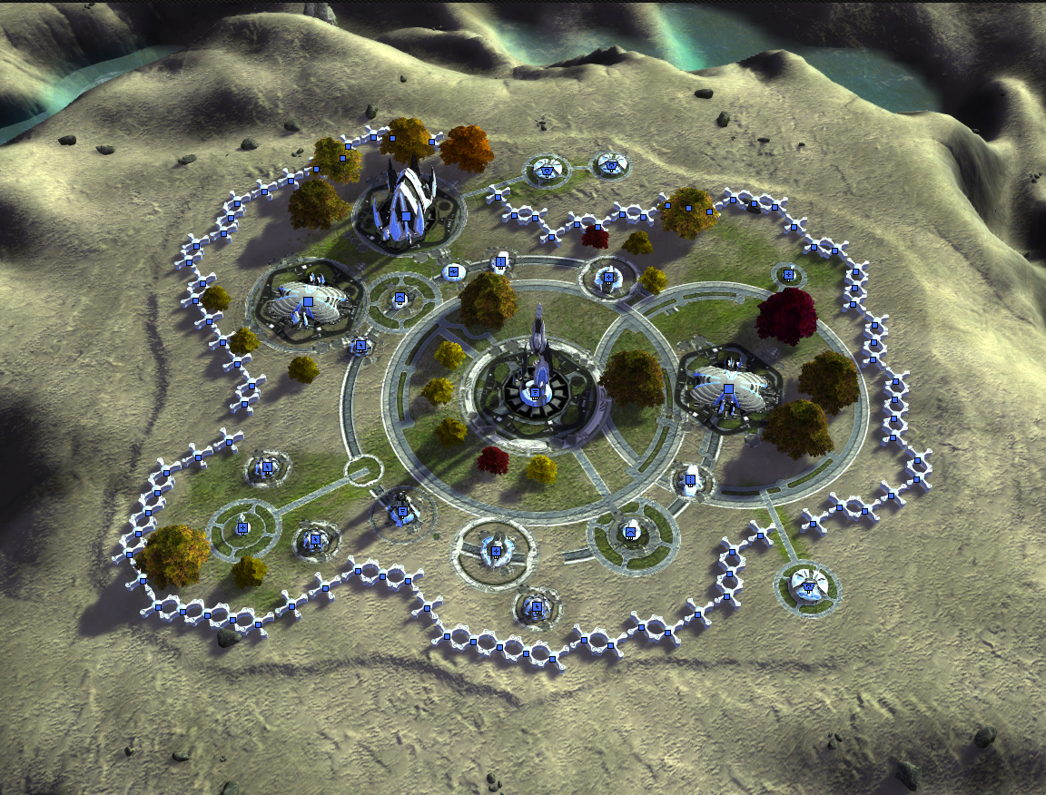
In style with the Aeon orderliness, a lot of props and decals were very precisely placed. To say that this was tedious work is an overstatement, but at least it looks good. More sexy pictures will be posted in the post discussing the final version.
Second feedback round
The second round for feedback was blessedly much shorter: the changes made to the map were well received and solved many of the previously identified issues.
The way the slots were laid out meant that every slot has a lot to do: both back slots had to go into navy as well as air, and also had to walk their commanders to the middle. Meanwhile, the center player had a bit more time in the beginning where they would be on their own, and would have to focus on aggressively spamming T1.Small changes were made based on the feedback: the defences for the centerpiece were slightly reduced, a few mexes were adjusted, and a small pathing issue with the terrain resolved. The main point raised was that the islands in the top left/bottom right corner were too difficult to get for the navy player, and were generally too high. These issues were addressed in the final version.
Version 3
The final touches to textures, decals, and terrain were made. The corner island were lowered, the map-wide shadow, normal, and texture decals finalised, and some extra tree-props added. Some subtle waves were added to the water as well. Pretty!
AI markers were placed to support AI players, and a T1 AA was placed on the top left/bottom right islands added in a place that mostly makes it more difficult for the air player to reach the island before the navy player does.
An issue with flickering map-wide decals was found and solved: in maps with large differences in terrain, map-wide decals might sometimes produce weird visual artifacts and flicker. Solving this took some debugging and more time than I am willing to admit. To save anyone else the time and effort: placing the two map-wide assets at the bottom of the decal stack solved this issue. One remaining issue where some decals pop into view, rather than gradually fade into view, remains, but this issue will be fixed by the upcoming FAF update.
With that, the map was finished. Details, pretty pictures, and highlights will be showcased in the next post.
-
Gaea tutorial: Producing terrain masks
The various map projects I've made have all been made possible by Quadspinner's Gaea, a terrain design application for VFX and games. Gaea is an industry standard and a great tool to significantly speed up creating or increasing the complexity of masks, heightmaps, and decals. Because of FAF's peculiarities and the fact that the game is more than a decade old, the process of producing masks using Gaea is a bit involved. Being the shiny beacon of enlightenment that I am, I will here share my workflow for making these masks.
This tutorial assumes you've got a basic understanding of image editing and FAF mapping. Additionally, it is suggested you familiarize yourself with the concept of visual node based programming. A very rudimentary understanding of Gaea is also required: while I will discuss the relevant nodes and how they work, I will leave familiarizing yourself with the software for self study. Watch a few youtube tutorials on the basics, or read the general introduction to Gaea here.
Required for this tutorial is a copy of Gaea (the indie version is free to use and more than sufficient for maps up to 20km), which can be downloaded here. Additionally, an image editor such as Photoshop or Gimp is required, though the free to use online photoshop-clone Photopea works fine too, as is the FAF map editor.
Footnotes marked as '[0]' where needed. Notes are added to the bottom of the tutorial.
When specific nodes are referenced, they are highlighted like this:
Node. Specific parameters for these nodes are written like this:Slope, 30, 90, 0, to specify aSlopenode with Parameters 30 (min), 90 (Max), and 0 (Falloff).Terrain, masks, and stratum layers
A quick recap of the basics:
Once the terrain of the map has been created, usually the next step is applying textures. To apply the textures to specific spots, masks are drawn. At most, eight masks can be used per map. Masks are greyscale images, where the intensity of the pixel relates to the opacity of the texture. These masks can be imported and exported to and from the FAF editor.The mask files usually have nearly the same resolution as the heightmap, with one small caveat: while heightmaps have resolutions of 2^n+1, masks have resolutions of 2n. Consequently, a square 10km map has a heightmap of 513 x 513px, but masks of 512x512px.[1]
Furthermore, masks have several strict requirements:
- Masks are 8-bit RGB, non-interleaved .raw files
- Only greyvalues of 128 to 256 (50% white to 100% white) are used to assign textures. Values below 128 are ignored. (See figure 1)
- Due to a bug in the shader code, the normals of a layer are applied using the greyscale values of 0 to 256. Consequently, you may see the normals of a layer applied in sections where you do not see the albedo of a texture applied.[2]
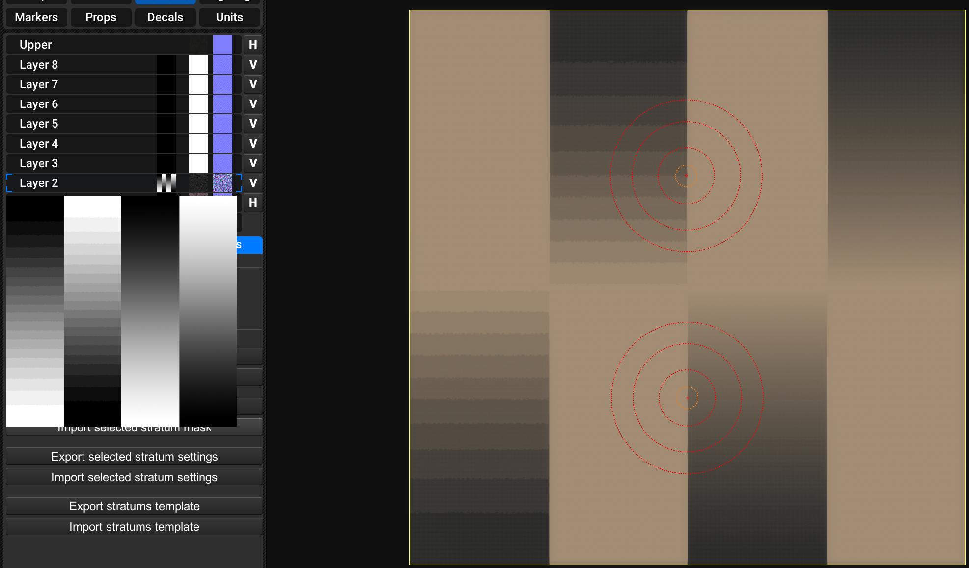
Figure 1: Showing how greyscale values below 128 (50% white, or grey) are ignored.
The workflow summarized
In short, the workflow to create these masks is as follows:
- The terrain is created in or loaded into Gaea
- Several masks are defined using the various relevant nodes
- The masks are exported as .png8 files
- The greyscale value of the masks is adjusted
- The masks are exported as .raw files
- The masks are imported into the editor
For my map Project Dust, the masks when exported at step 3 (before the greyvalues are adjusted) look like this:
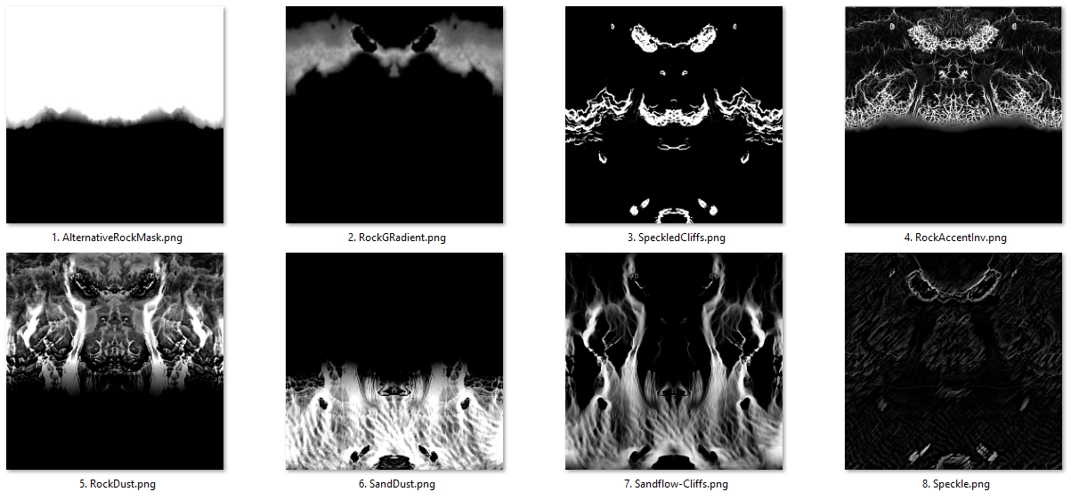
Figure 2: An overview of the exported masks for my map Project Dust. Notice how each masks highlights different features.
After adjusting the greyscale value, the final mask looks like this (example of mask #5):
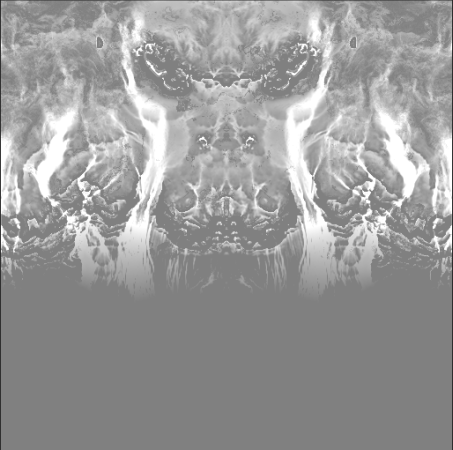
Figure 3: Grey-scale adjusted copy of mask 5.
Loading the terrain in Gaea
To export terrain from a map made in the editor, open the map in the FAF editor and navigate to the Terrain tab. Under the Heightmap subtab, you will find a button labelled "Export heightmap". This will export the heightmap as a 16-bit RGB, non-interleaved, IBM-PC (34-12) .raw file.
This file can be loaded into Gaea using the
Filenode. Add a File node to your workspace, and load in the exported heightmap. Due to differences in how Gaea and FAF interpret heightmaps, it may be required that you manually rescale the terrain vertically. The easiest way to do this is by using theRaiseadjustments, which you can find by selecting the node and clicking the corresponding button at the bottom of the node's side-panel. Increasing theMultipliervalue to scales the terrain up vertically. It is my understanding that for the subject of masking this scaling is optional, though I personally have found it easier to work at a scale as similar as possible to the FAF editor.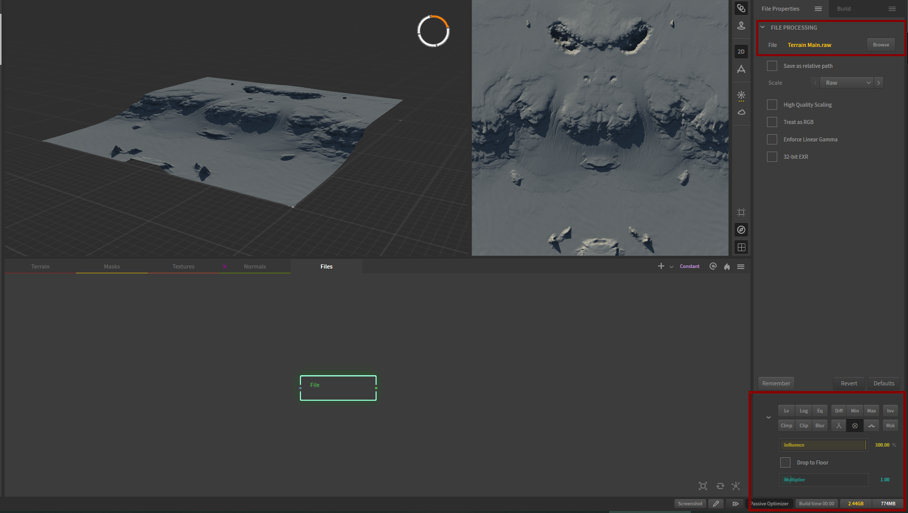
Figure 4: A file node is added, and the heightmap of Project Dust loaded. The Raise adjustment is selected, but in this instance the multiplier is set to 1.000, so the terrain is not scaled.
Defining masks
As shown above in Figure 2, your aim should be to create distinct layers with specific textures in mind. The masks will allow you to distinguish specific features from the total terrain and to add extra detail to large areas that would otherwise be very homogenous. Using these masks, you can prototype a set of colours and textures within Gaea, and later use the masks for texturing your map. (Setting up this system within Gaea will be the topic of another tutorial).
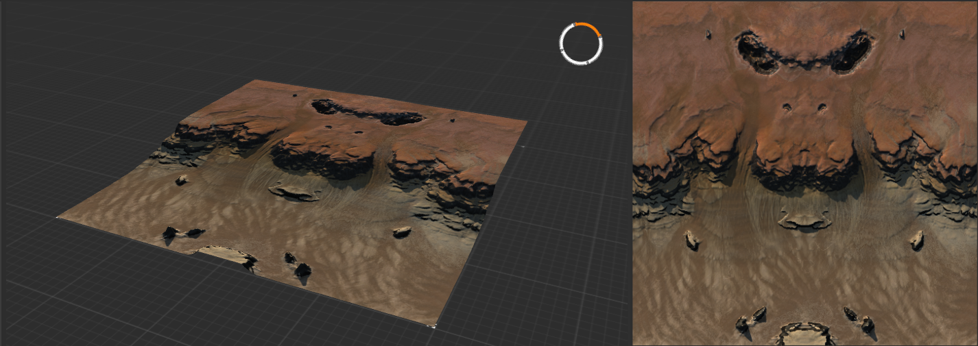
Figure 5: A mockup of the textures using the generated masks in Gaea
When designing a set of masks, I aim to have at least the following:
- One mask for each of the types of terrain
- A mask to distinguish the cliffs and unpathable terrain
- A mask for dirt, dust, and soil
- A mask for highlights
More masks may be added to add complexity to large sections of one type of terrain.
To create these masks, most commonly the nodes in the Data section are used. These nodes allow you to select certain parts of the heightmap, and include
Height,Slope,Soil,Curvature,Flow, andTexture. Where necessary, the outputs of these are blended and combined using theCombinenode.To select all the cliffs on Project Dust, for example, I used the following setup:
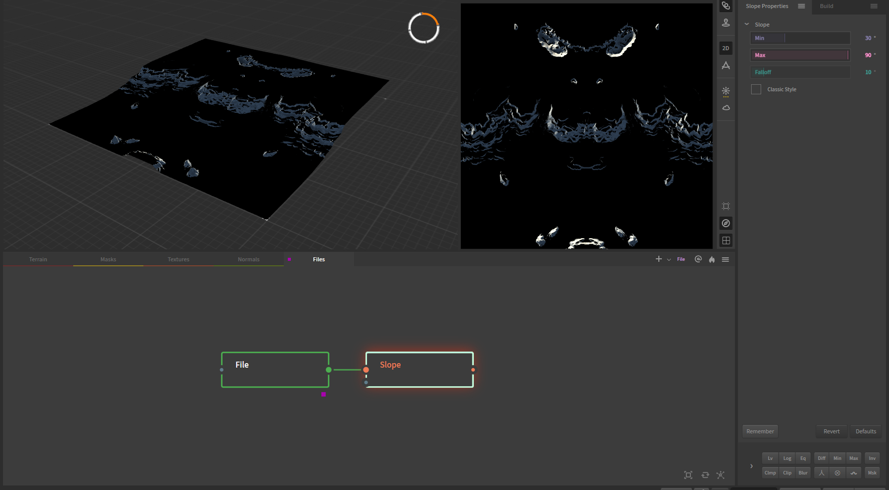
Figure 6: Setting up the cliff mask
First, I chained a
Slopenode to theFilenode. TheSlopenode has three main parameters: Min, Max, and Falloff. By adjusting the Min and Max values, you select all terrain that is sloped with an angle in degrees between those two values. The falloff value specifies the feathering of this selection; a falloff value of 0 results in a sharp delineation of the two selected and unselected regions, while the border gets progressively blurred as the value increased.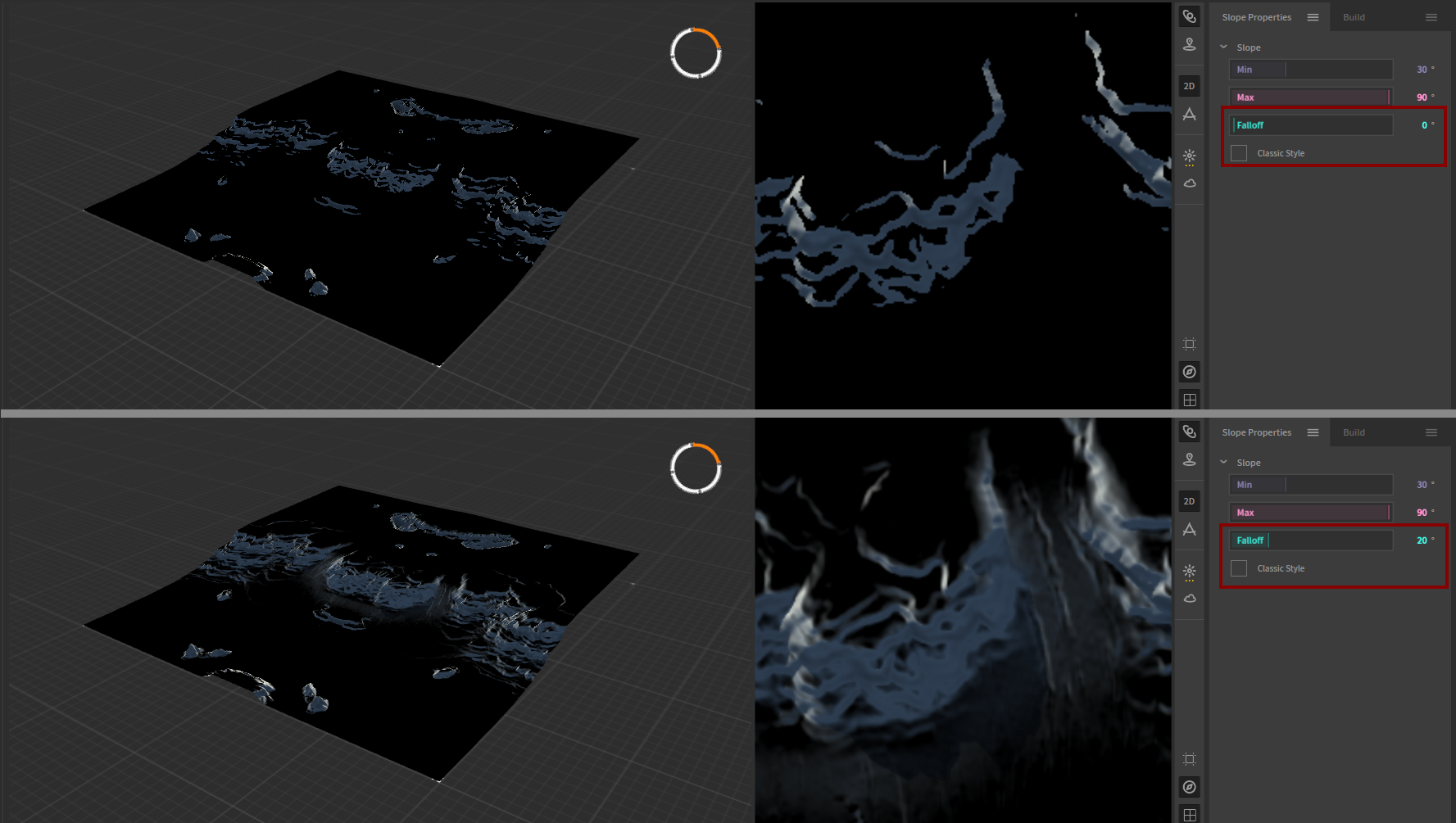
Figure 7: The effect of increasing the falloff value
Similarly, the
Height nodeallows you to select terrain at certain relative heights.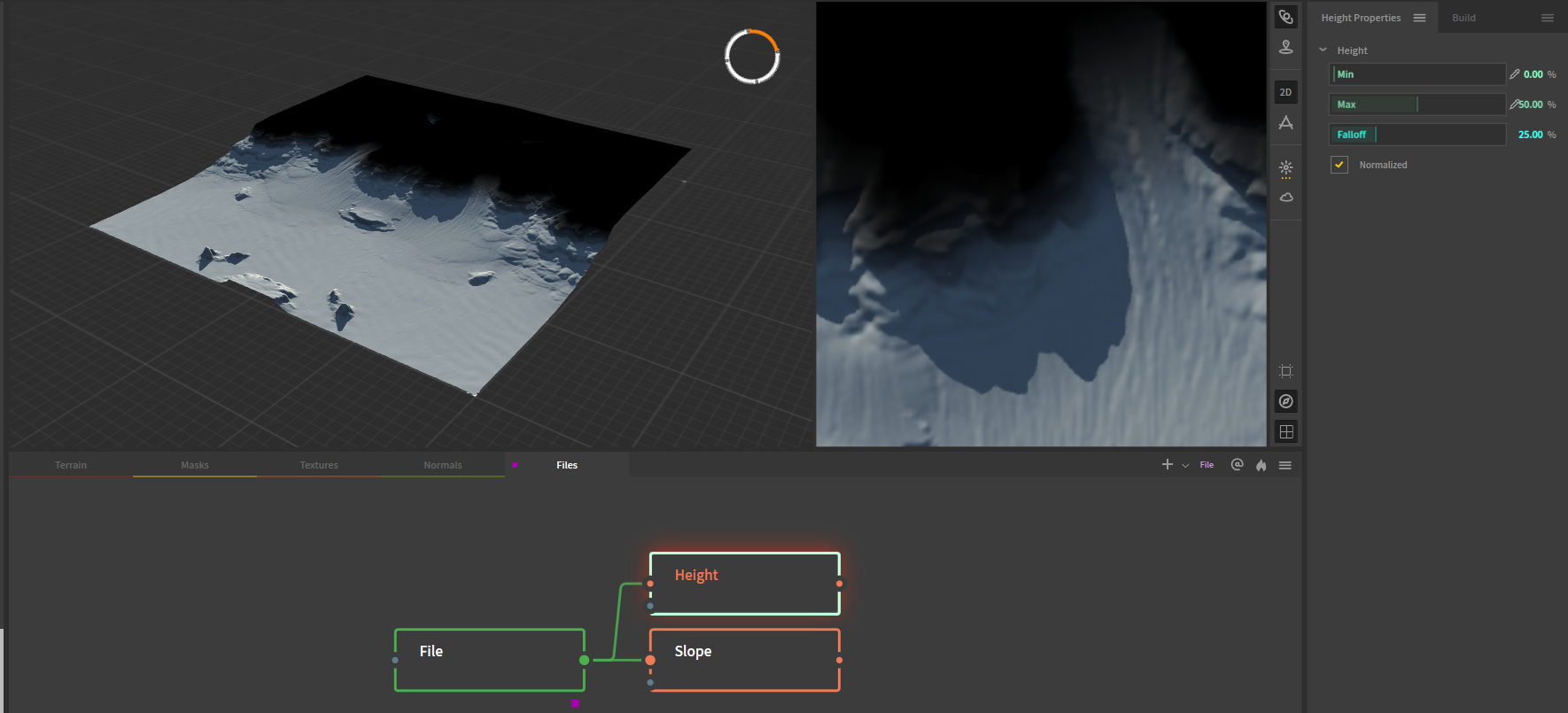
Figure 8: The bottom 50% of the terrain is selected, and the selection fades out over the next 25%.
These and others may be blended together to make selections of selections, or to add different selections together. If you want, for example, to only highlight all the slopes at the top of the terrain, you could select all the slopes (
Slope: 30, 90, 0), selecting the bottom 50% of the terrain (Height, 0, 50, 10, Normalized), and subtracting the Height from the Slopes (Combine, Subtract, 100%).Alternatively, you may select the top 50% of the terrain (
Height, 60, 100, 10, Normalized) and chain this node as a mask into a slope node (Slope, 30, 90, 0).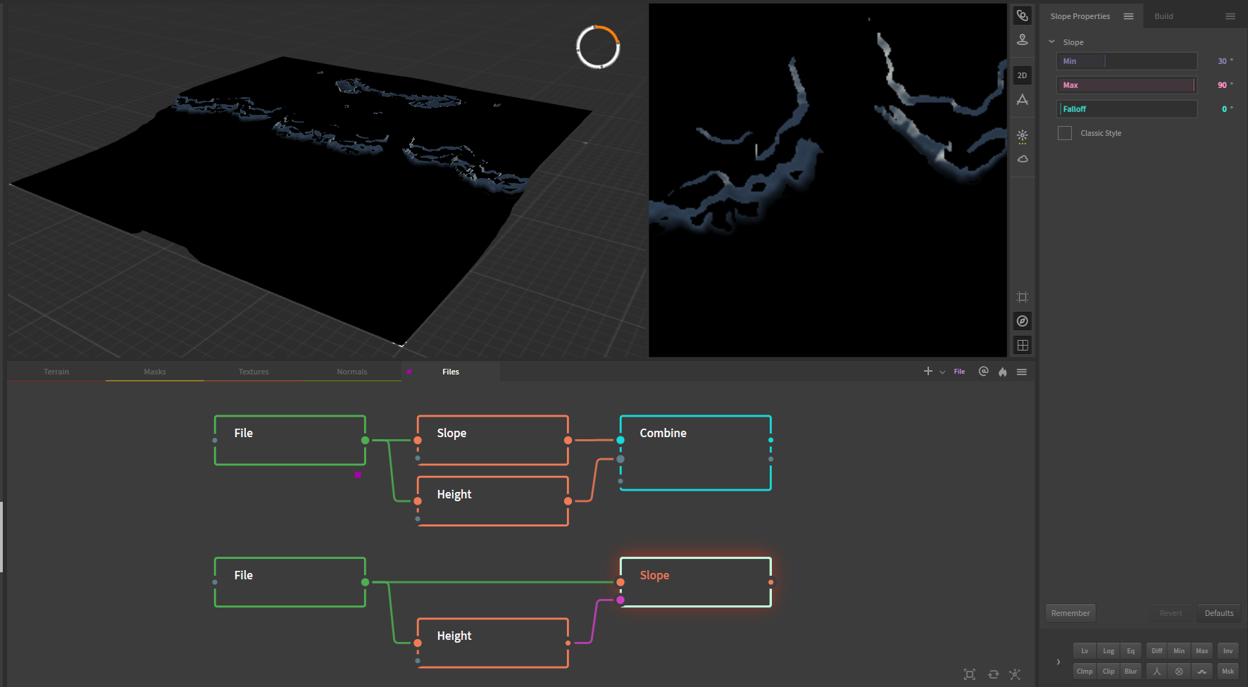
Figure 9: Two approaches to combining height and slope selection nodes to select only the slopes in the top 50% of the terrain.
The process of combining the various nodes will take some time and effort, and involves a lot of finetuning of values to get the masks exactly as you need them to. To keep all the masks organized, you may choose to rename the nodes corresponding to what terrain they select. For Project Dust, the final node tree to select all masks looked like this:
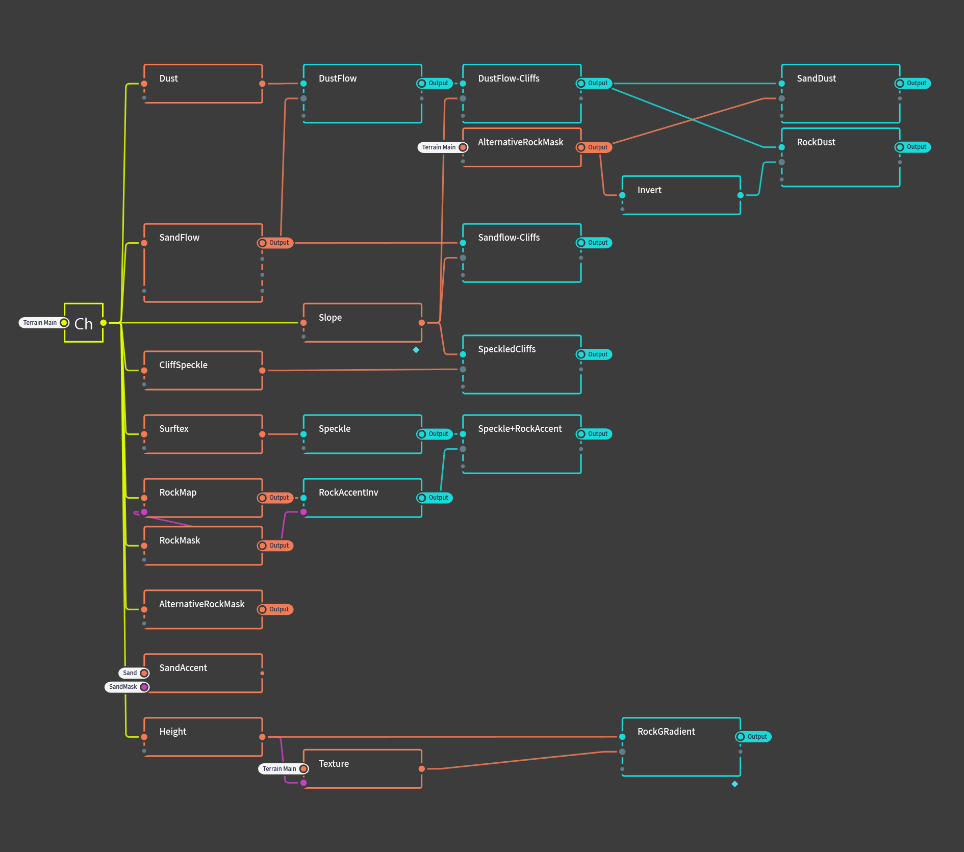
Figure 10: Overview of the node tree generating the masks for Project Dust
This somewhat complex graph might look a bit daunting at first, but it is important to realise that these structures are built one node at the time, logically following from and combining with the previous nodes.
For the curious reader: the little tags on some of the nodes are called portals, and allow for connection between nodes that do not share the same worksheet. For an introduction on portals, check the Gaea documentation.
Exporting masks
To export the masks, select the relevant nodes and press F3, or right click and select Mark for export. The marked nodes will now show up under the Build tab in the top right. Adjust the relevant settings:
- Change the filetype of all masks to .png8
- Method should be left on Normal Build
- Resolution should be set to the size corresponding to your map's heightmap. (See note about resolution above)
- Colorspace should be left on sRGB
- Range should be left on Raw, although alternatively this may be set to
Remapped, 0.5, 1to skip the step of adjusting the greyscale values of masks.[3] - Baked Cache may be left on Use
After selecting where Gaea should dump the generated files, you can render the files by pressing Start Build.
Adjusting masks
Two steps remain before the masks can be imported to the FAF editor. First, if the masks were exported with the Range setting left on Raw, the greyscale values have to be adjusted so that only values of 128 and up are used. Masks that were exported using the Remapped setting may skip this step.
Adjusting the greyscale values is as simple as adjusting the levels using your preferred image editing software.
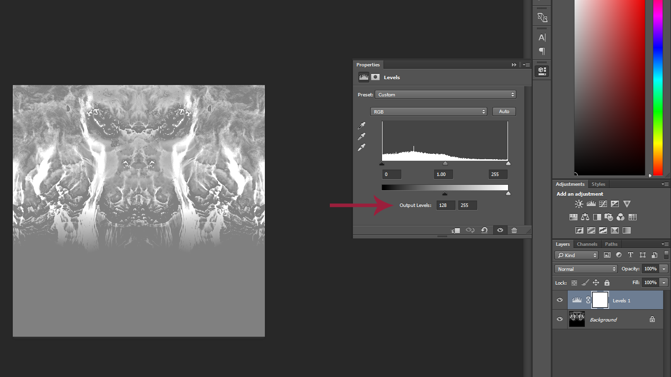
Figure 11: Adjusting the mask using the levels adjustment layer in photoshop
Similarly, encoding these files as .raw can be done in Photoshop or alternative image editing software. A great free and online alternative is Photopea, for those who do not own Photoshop.
To save the masks as .raw filetype, make sure of the following:
- The files are 8-bit RGB (should be fine as long as you export as .png8 in Gaea)
- The file is saved as .raw., 8-bit , 1-channel, non-interleaved, at IBM PC or 34-12 byte order.
- Double check that the resolution of your mask is correct
Importing masks
Your masks are now ready to import into the FAF editor. Navigate to the textures tab, select a stratum, navigate to the Settings subtab, and click the Import selected stratum mask button. After loading the mask, the texture for that stratum should now appear where the mask exposes them.
Common mistakes
"Hey", you say, "I see weird lines in my masks. What gives?"
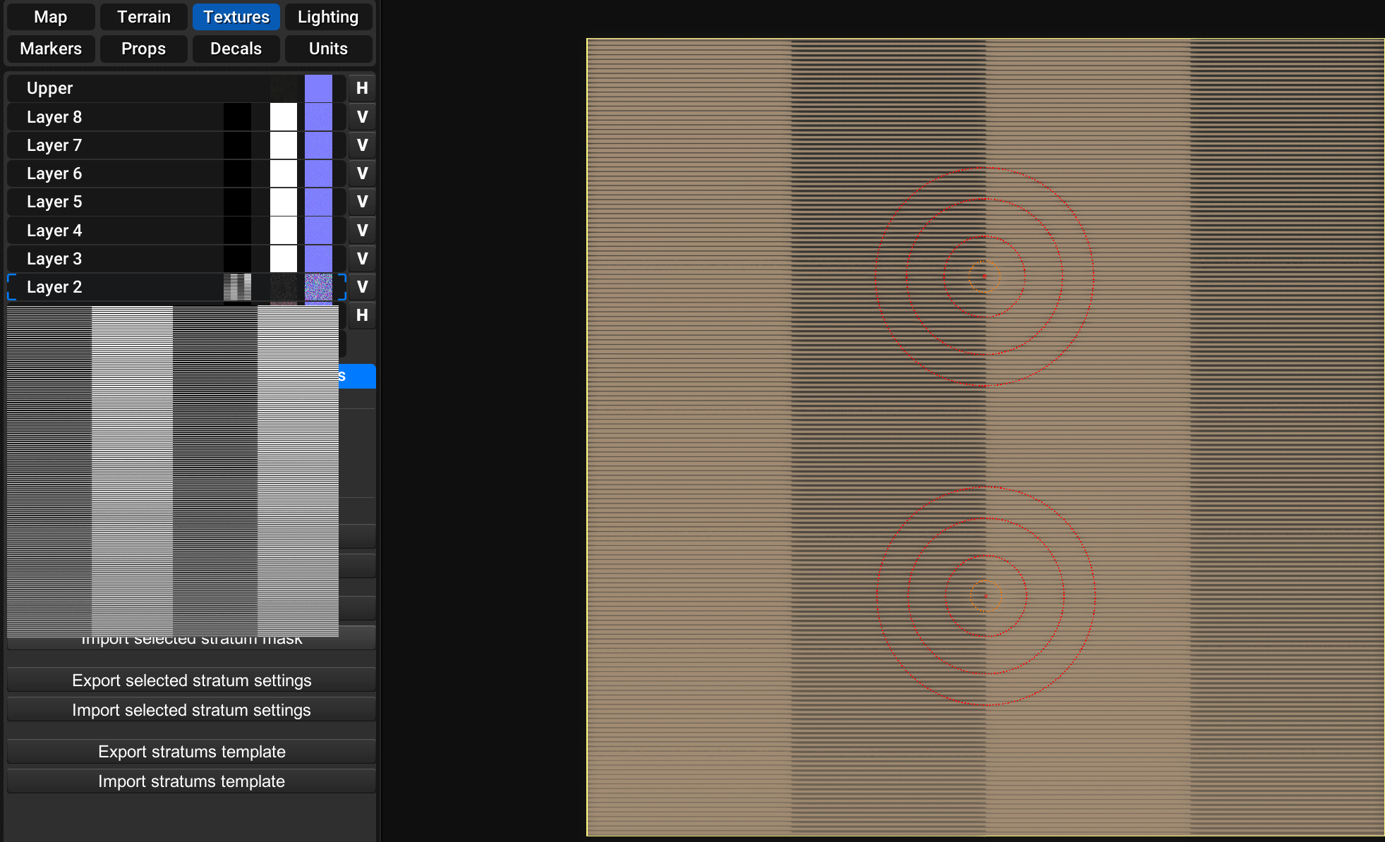
If you see something like the above, verify if you followed the instruction on the strict requirements above. Likely, you saved the .raw file as either an interleaved rather than a non-interleaved .raw or you exported the image as an 16-bit .raw.
A very common issue is a mismatch between the resolution of your mask and the resolution the map requires you to provide. This may be caused by [1] and should be debugged by creating a mask in the FAF editor, exporting the mask, and verifying the resolution in an image editor.
Remaining questions
If you are left with questions or need help, your best bet is to check with people in the FAF discord Mapping-General channel. Alternatively, you may send me a PM on discord, or leave a message on this forum.
Footnotes
[1]: The GPG editor is known mess with these values. Any map that has touched the GPG editor at any point is suspect and the resolution of the masks should be verified by exporting the mask file and opening the image in an image editor.
[2]: There is a semi-functional workaround to prevent the normal maps from showing where they shouldn't. Finding this workaround has been left as an exercise for the reader.
[3]: If you are planning on using some of these masks in photoshop for manual adjustments or the like, it is best to export using raw range setting. This setting should also be used if you are attempting workarounds for the issue mentioned at [2]. The quickest and easiest method is to export as Remapped, though.
-
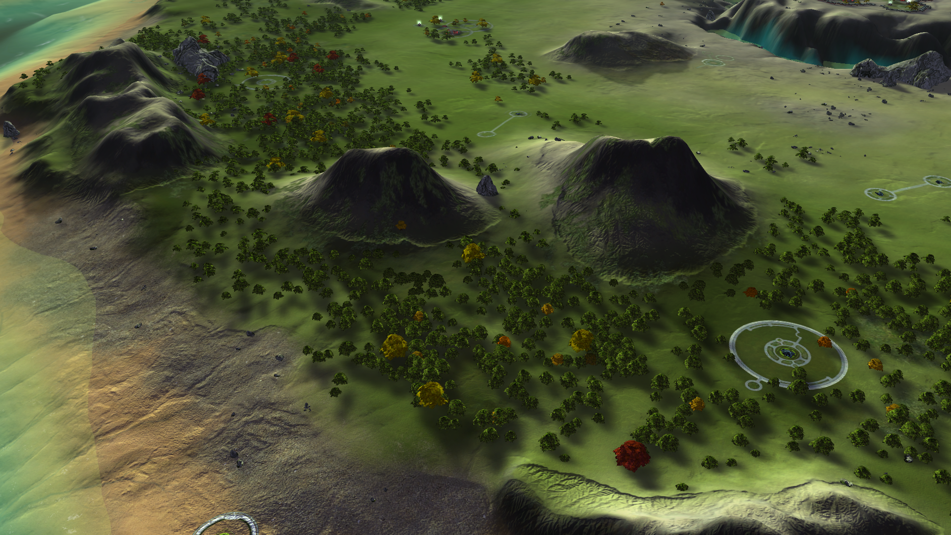
On this classified planet claimed by the Aeon Illuminate, researchers worked years on developing novel surveillance technology. The research, codenamed Project Luminary, resulted in a working prototype, the creation of the Eye of Rhianne, and later on even a minitiurized version which can be installed on the commander. Ever since, the surveillance abilities of the Aeon are without peer. // Licensed under CC BY-NC-SA 4.0. Contact the map author on FAF discord for feedback. This map is compatible with AI.
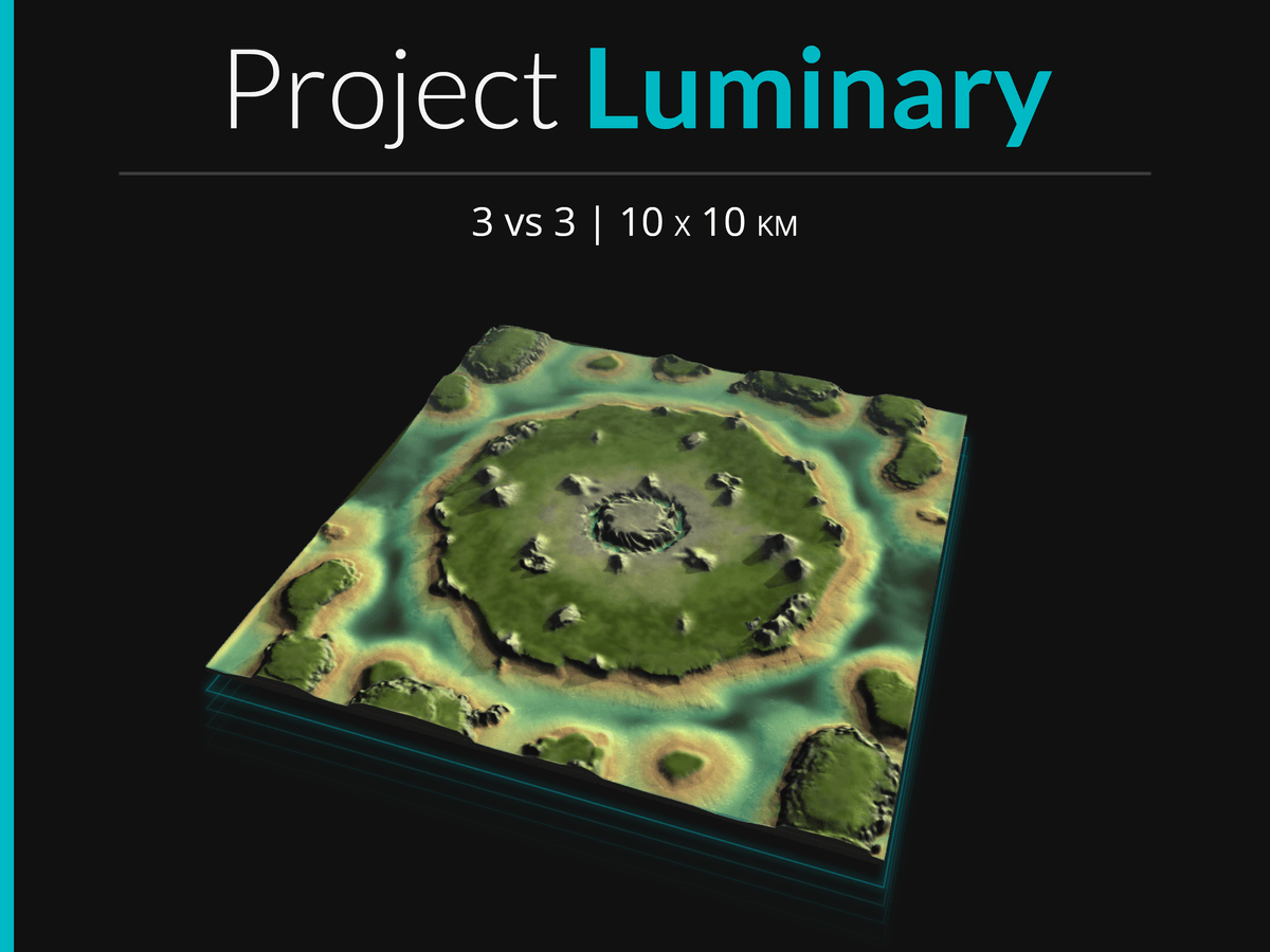
Project Luminary is a 10x10km map, and is my entry for @Jip 's 'Princess Burke' Mapping tournament. This section of the secret and classified Aeon planet is designed for six people and is best played using the Aeon race, as the terrain allows hover tanks to shine.
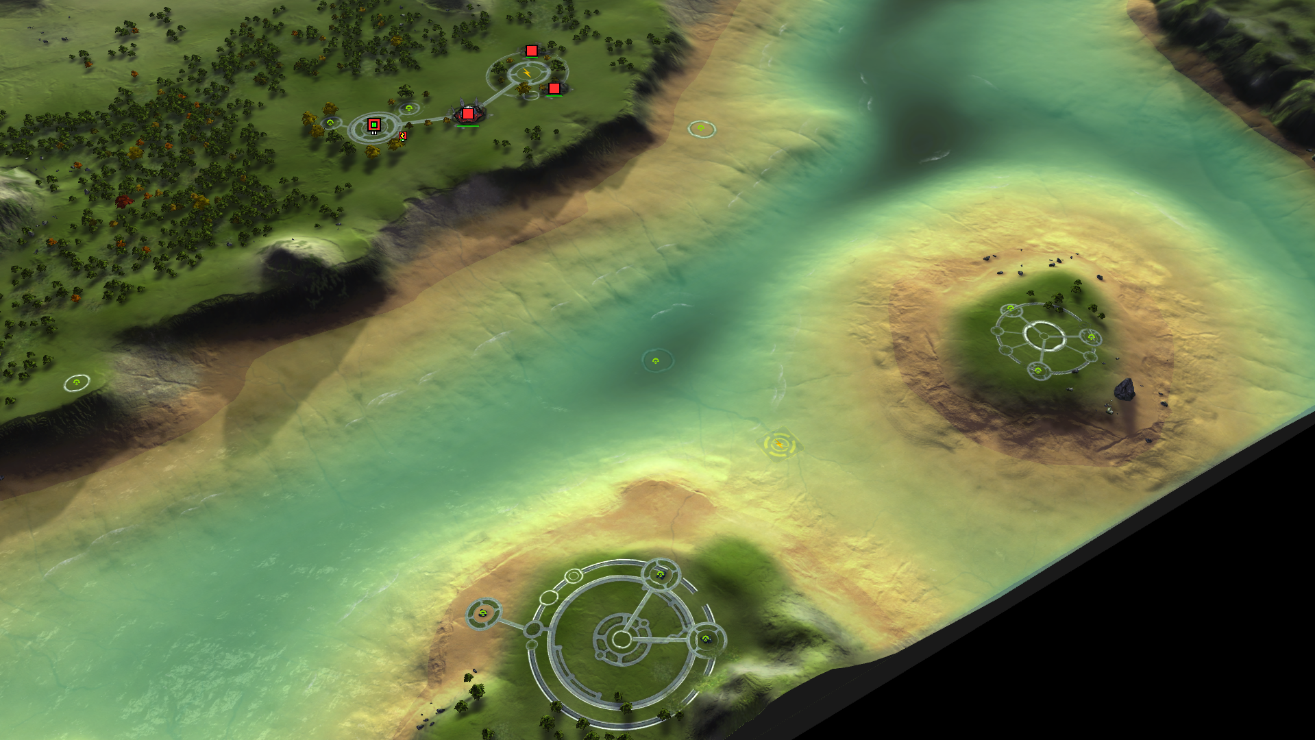
Expect aggressive gameplay: players are likely to have to multitask navy, air, and land at the same time, as many mexes are easily raidable by all three options.
The map is licensed under CC. BY-NC-SA 4.0 and is compatible with AI.
Design
As the tournament for which this map is my submission requires an Aeon-themed map, several aspects of the design—both major and minor—are themed to reflect this.
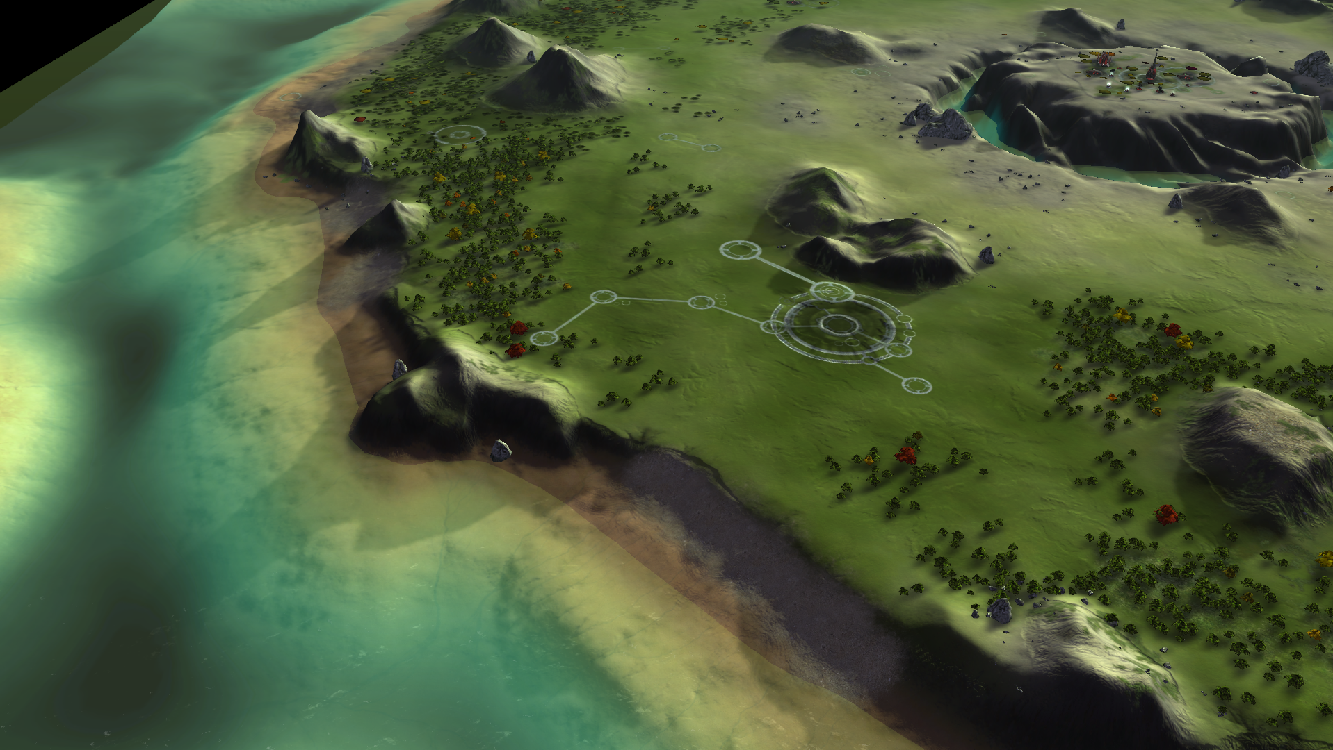
I decided to imagine a map that would serve as the location for the research station that developed the Eye of Rhianne. The map design somewhat resembles an eye, with a pupil-like platform in the middle and an 'iris' as the main island. The name is similarly derived from this concept. A luminary is someone who enlightens others, or refers to 'that which lights up the surroundings'. Given that an Eye of Rianne literally lights up the darkness, the name is a great fit.
Key recurring features are circles, geometric shapes, and precisely placed props. (I spent an inappropriate amount of time carefully shifting the decals, buildings, and props until they lined up exactly. Please someone notice T.T)
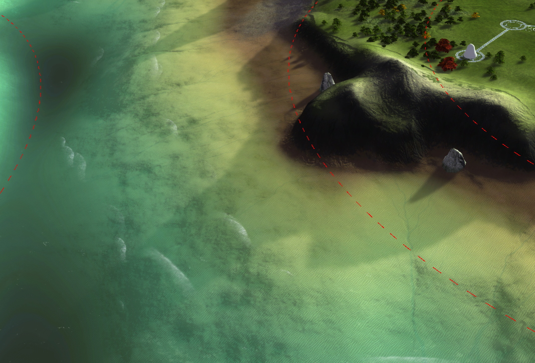
Frigates will be having a fun time contesting mexes on the shores, but will have to keep in mind that the shore will never be far away, and Aeon hover tanks might want to use the same space to flank around any PD installations.
Other fun facts:
- This map uses just over 2000 decals, two of which are a map-wide normal map and a map-wide Albedo/Shadow decal
- The map-wide albedo is mostly transparant, but helps a lot with color correction and cliff details
- The map-wide assets took 2 hours to render at the required 8k resolution, during which my PC froze and could not be used for other stuff. This had to be done four times. (My PC is ten years old and desperately needs a replacement. If you're reading this and you're rich, please buy me a new pc. Help.)
- There are only 4 circle-type Aeon-ish decals. To create the various patterns, I stacked and combined these in different combinations to keep everthing interesting. Getting everything lined up was super fiddly and a massive pain and please don't make me do this again.
- The centerpiece features 3 small transport ships (because naturally, the people living in that base have to get off their little platform somehow.) These transports have their own little designated landing zone, though at the start of the game they decide to relocate for some reason. (Compare the third and last picture). I suspect either some roughness in the terrain or too close proximity to other structures, but I haven't figured that one out yet.
- I added very subtle waves and clouds because they look beautiful. The clouds are only visible if you zoom all the way out, because it's deeply annoying to not be able to properly see the things you're trying to focus on.
- Not including whatever mass you get from the structures (about 5k, estimated), the map contains 23K mass reclaim and 65K energy reclaim. Most of the mass is stuck in little tiny rocks, so while a steady stream of reclaim is available, we shouldn't see too large of spikes in income.
Images
-
 I IndexLibrorum referenced this topic on
-
I IndexLibrorum referenced this topic on
-
I IndexLibrorum referenced this topic on
-
I IndexLibrorum referenced this topic on
-
I IndexLibrorum referenced this topic on
-
I IndexLibrorum referenced this topic on
-
I IndexLibrorum referenced this topic on
-
I IndexLibrorum referenced this topic on
-
I IndexLibrorum referenced this topic on
-
I IndexLibrorum referenced this topic on
-
I IndexLibrorum referenced this topic on
-
I IndexLibrorum referenced this topic on
-
I IndexLibrorum referenced this topic on
-
I IndexLibrorum referenced this topic on
-
Gaea tutorial: A basic introduction to mapping with Gaea
The various map projects I've made have all been made possible by Quadspinner's Gaea, a terrain design application for VFX and games. Gaea is an industry standard and a great tool to significantly speed up creating or increasing the complexity of masks, heightmaps, and decals. Because of FAF's peculiarities and the fact that the game is more than a decade old, the process of producing these assets using Gaea is a bit involved. Being the shiny beacon of enlightenment that I am, in this tutorial series I will explain my process for creating all the relevant map assets in gaea (see figure 1). This specific tutorial will discuss the basics of Gaea and how it can be used to create the main heightmap for your terrain.
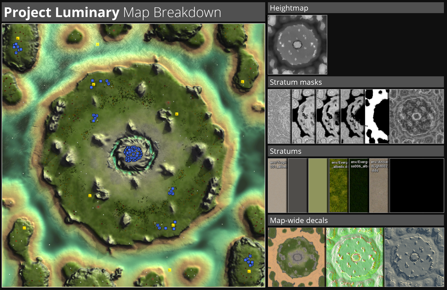
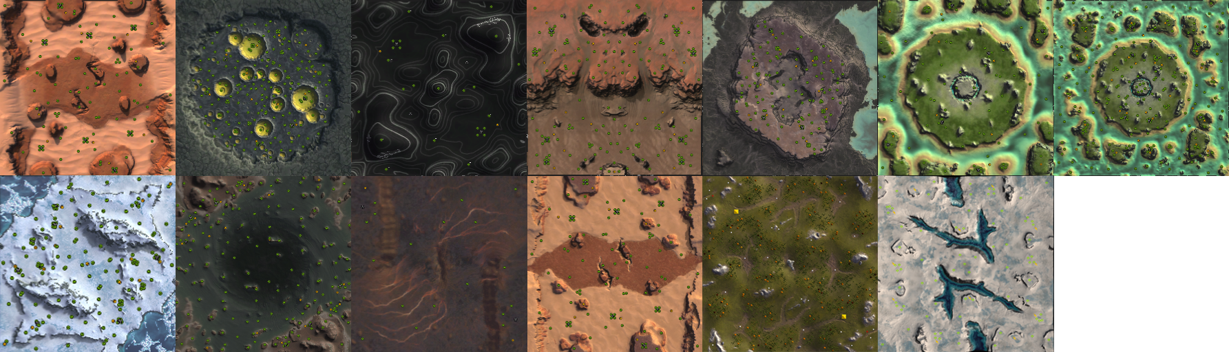
Figure 1: a breakdown of the map Project Luminary to show all the assets generated in Gaea. Note: some of the stratum textures are stock-FAF textures and were not created in Gaea, but are here included to illustrate the different components of the map.
Prerequisites
This tutorial assumes you've got a basic understanding of image editing and FAF mapping. Additionally, while this specific tutorial will explain some of the basics of visual node based programming, the technique Gaea uses to create the assets, it is recommended that you take some time to familiarize yourself with the concept and Gaea in particular. This 6-minute video is highly recommended, as is giving the general documentation for gaea a read. Using this node system may look daunting at first, but is very intuitive and easy to learn.
Required tools
Required for this tutorial is a copy of Gaea (the indie version is free to use and more than sufficient for maps up to 20km), which can be downloaded here. Additionally, an image editor such as Photoshop or Gimp is required, though the free to use online photoshop-clone Photopea works fine too. Finally, you need to have installed the FAF map editor.
Footnotes marked as '[0]' where needed. Notes are added to the bottom of the tutorial.
When specific nodes are referenced, they are highlighted like this:
Node. Specific parameters for these nodes are written like this:Slope, 30, 90, 0, to specify aSlopenode with Parameters 30 (min), 90 (Max), and 0 (Falloff).Introducing Gaea
Gaea is a graph-based application for creating terrain and focussed on providing techniques to simulate realistic erosion. To create these terrains, different nodes are linked to eachother. Nodes affect or combine with other nodes to create complex shapes and structures. While working in Gaea, you will navigate between several panels.
The workspace
As of June 2023, a typical workspace in Gaea might look like Figure 2. The workspace can be configured to your preferences, with different panels moved or scaled. The largest part of the screen is taken up by the viewports and the graph surface. The viewport shows you the terrain and masks, the view of which can be rotated, scaled, and panned. Optionally, you can press the
2Dbutton in the viewport toolbar to show the second, top-down, viewport. Below the viewports, you will see the graph surface, where your nodes and their connections are displayed. Clicking on a node will show the contents of that node in the viewports.! Tip: you can lock the viewport to show one specific node by selecting the node and pressing
Fon the keyboard. The node will be marked with a small green circle on the bottom right of the node to indicate the viewport is locked on that node. This is very useful when you are adjusting parameters of nodes earlier in the chain, but want to see the result on a specific node later in the chain. Press F again while selecting the node to unlock the viewport.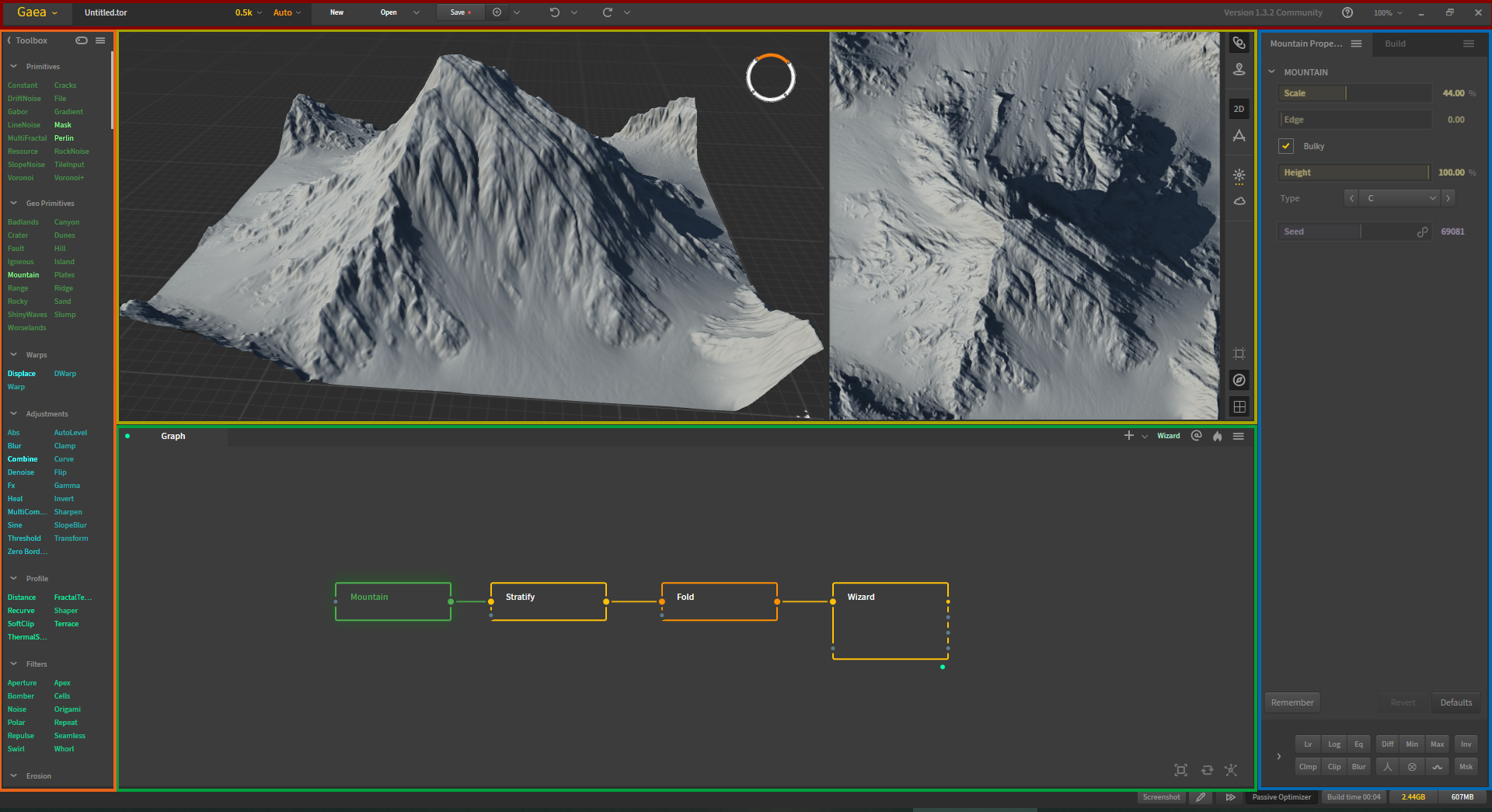
Figure 2: Typical workspace of Gaea. Colored accents added to highlight the different panels. Red: Main toolbar. Orange: Toolkit containing various nodes. Yellow: Viewport, 2D viewport, and viewport toolbar. Green: Graph surface. Blue: Properties panel.
The toolbox contains all the nodes you can put onto the graph surface. Nodes are grouped by type, and have a specific colour to signify which group they belong to.
Clicking on a node will also reveal the properties panel for that node. Here, you can adjust the effect or contents of the specific node.Above all the other panels is the main toolbar, which contains a few important things to discuss. First, the viewport resolution can be selected in this panel. It is generally recommended to select the resolution that you will be exporting your heightmap in. Gaea recalculates the terrain and parameters of the nodes every time you switch resolution, and the resolution can drastically affect how the terrain is shaped. Aside from the obvious increase in fine details, you might find that elements have changed shapes or moved when comparing different resolutions.
! As the terrain changes based on the resolution it is rendered in, creating high-resolution map-wide decals might result in some mismatch between the heightmap and the decals. A method to prevent this will be discussed in the tutorial on map-wide assets.
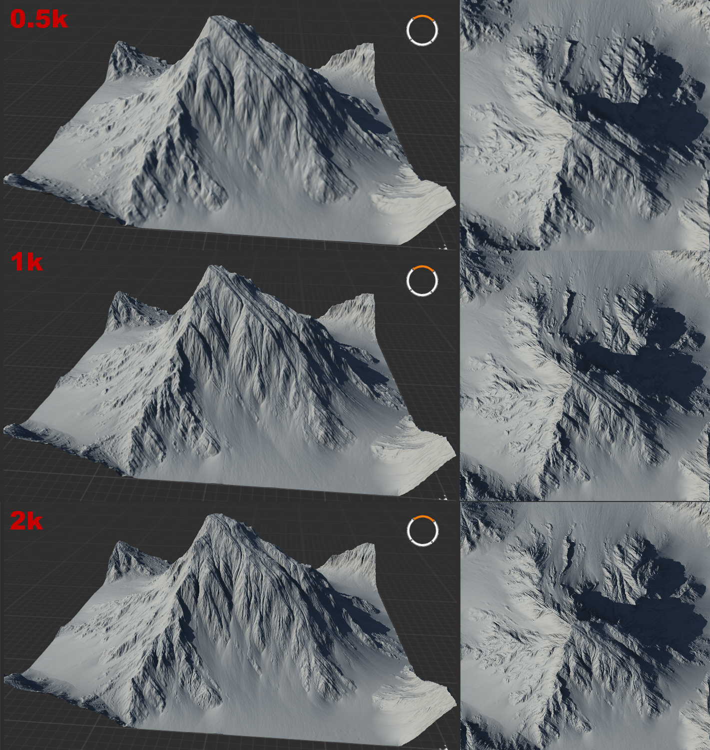
Figure 3: Showing the differences between the viewport at 0.5k, 1k, and 2k resolution. Note the increase in fine details.
Another important section of the main toolbar is the save button. Attached to the save button is a smaller button labeled with
(+). This button will create a version-copy of your project: if a project is named 'Project Luminary V1', clicking this button will create a new savefile labelled "Project Luminary V1001". The next time you click the button, the new savefile will be labelled "Project Luminary V1002". I cannot stress enough how important it is to regularly create a new version. Since before I started using Gaea, the undo and redo buttons have been rather dysfunctional. Maintaining a recent version of your project will ensure you do not lose large sections of your work when you inevitably have to undo changes that the undo-button refuses to process. Note that the save-files Gaea creates are very small: do not hesitate to create new savefiles.Nodes and graphs
As mentioned, nodes are sorted by type and colored accordingly. Generally, basic nodes that create a type of terrain are green. Nodes that transform or adjust other nodes are generally light blue or teal. Nodes that apply erosion or aggressively 'damage' terrain are light or dark orange. A different, darker shade of orange is reserved for Data nodes, which are nodes that can be used to mask or select parts of the terrain based on certain parameters. When creating textures, the purple nodes will allow you to work with colour.
Nodes often have one or more inputs, and one or more outputs. A
Combinenode, for example has three inputs and two outputs. Hovering over the little dot marking the node's in- or output will show the name of the port and indicate whether or not a connection is required for the node to function. Ports that need a connection have the same colour as the node-type, while optional ports are grey. Additionally, many ports have a designated input for masks. Adding a node (A) to the mask-input of another node (B) allows you to restrict the effect of node (B) to the specific area determined by node (A). Connections to a mask-input are always coloured purple, to indicate the type of connection.Nodes that are improperly connected will have a red-dotted border and display the text "error". A node that has not been rendered yet will show as a blue-dotted bordered node. Clicking on this node (and, if required, un-locking any previously locked nodes from the viewport) will prompt Gaea to calculate the effect of the node and display its contents. Nodes that are selected will be marked with a blue glow. The node will then turn into a solid-bordered node, or if failed, be marked with an error.
! Sometimes, Gaea runs into an error that it refuses to get unstuck from. In most cases, it suffices to select the whole graph and press the 'Force a Refresh' button at the right bottom corner of the graph surface. If this does not resolve the issue, double check your connections (a common mistake is to connect to a secondary input rather than a primary input) or restart Gaea.
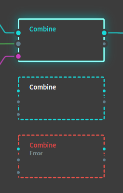
Figure 4: A properly connected and selected node, an unrendered node, and a node that was rendered but produced an error. Note how the first node has three inputs, one of which is a mask, and one output.
Node parameters
Each node has a particular set of parameters that can be adjusted to change the result of the node. Some of these have obvious effects: the Height parameter for the
Constantnode affects the height of the flat plane that the node generates. Common parameters include Scale and Seed. Seed in particular is a very powerful parameter common to nearly all nodes: changing the seed value randomizes the noise used to generate the effect of the node, which changes the outcome significantly (see figure 5). Other parameters are less intuitive, and require some experimenting to understand how the node is affected.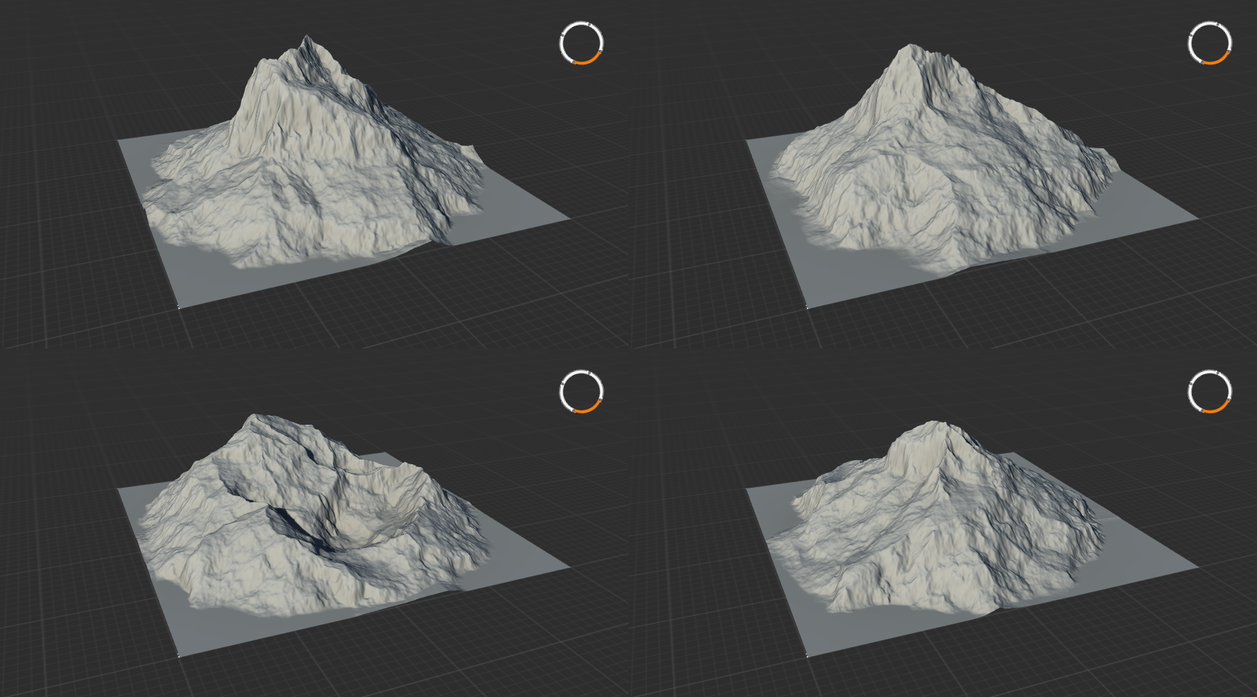
Figure 5: Four copies of a mountain node with identical settings but different seeds.
Creating a heightmap for FAF
Creating your first terrain
Primitives
Whether you have a design in mind or are hoping to combine nodes until something presentable falls out, you're going to want to start out with one of the primitives. This category of node is coloured green and serves as the basic building blocks for your terrain. Half of this category consists of 'plain' primitives: the
Constantnode produces a flat plane, theGradientnode produces a ramp or a cone. Different types of noise generators are included as well, such asGabor,LineNoise,Voronoi, andMultifractal.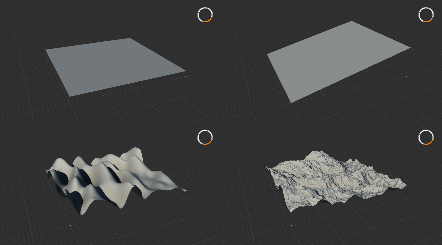
Figure 6: A selection of primitive nodes:
Constant,Gradient,Gabor, andMultiFractal.Geo primitives
The other half of this categories includes more complex presets of common terrain features. Among these Geo Primitives you will find nodes such as
Badlands,Crater,Mountain,Canyon,Dunes, andIsland(figure 7). Many of these advanced nodes can be recreated by combining 'plain' primitives, but as they are rather complex it is often easier to use the Geo primitives.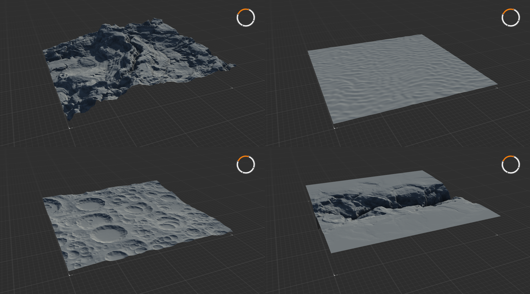
Figure 7: A selection of geoprimitive nodes:
Badlands,Dunes,Crater, andCanyon.Adjustments Nodes
To start adding things together, you'll need some nodes from the next main category: the adjustments nodes. The
Combinenode does what it says on the tin: you can combine two different nodes into one using different blending modes and strengths. Figure 8 shows the result of blending theBadlandsnode andCraternode from figure 7 together using four different blendmodes.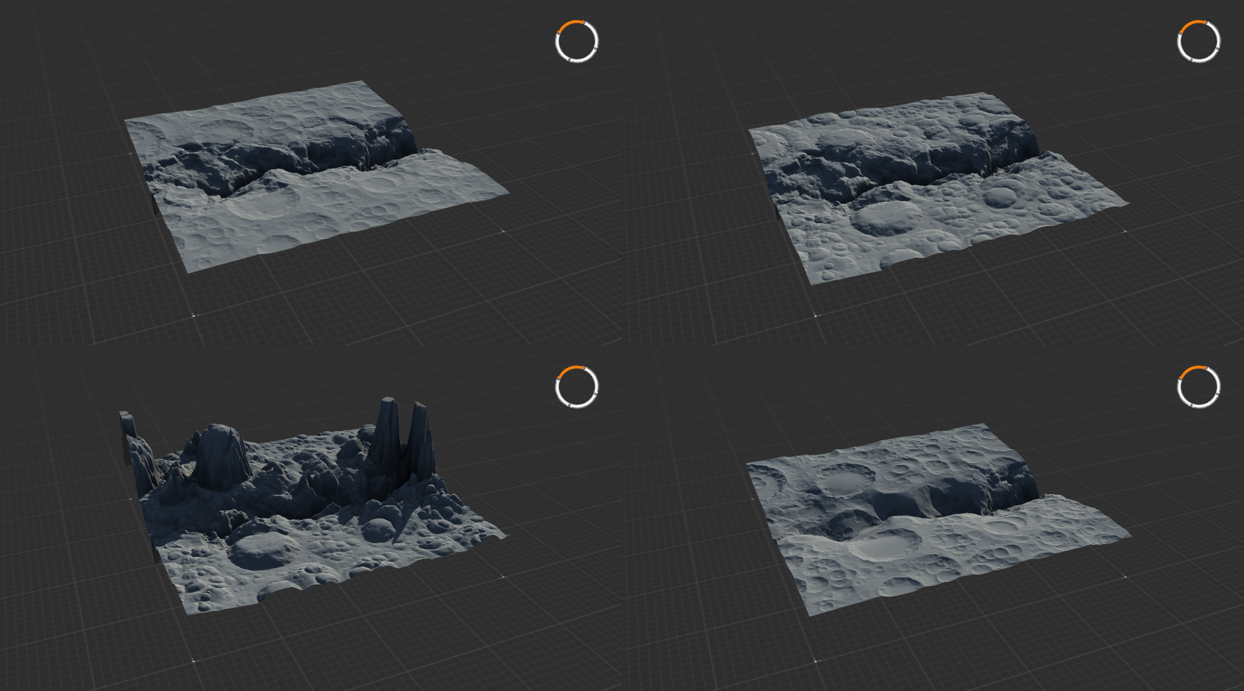
Figure 8: Blending
CraterandBadlandsusing the blending modes Embed, Subtract, Divide, and Insert.The other be scaled, rotated, and repositioned using the
Transformcommand, while theClampnode gives you good control over the global height of the terrain.
In my map Project Mesa, for example, I created the basis for the various pillars using aGradient, Radialnode, which I then repositioned and rescaled using theTransformnode, and merged with the main terrain using aCombine, Embednode.Erosion Nodes
Once the basic design of your map has been established, you might want to take a look at the various Erosion nodes. These nodes create rugged looking terrain, simulating decay over time from exposure to the elements. They can be applied to separate elements if you are combining multiple elements into one whole, be limited to specific areas using masks, or can be applied to the whole terrain at once. The
Wizardnode is a powerful erosion node with many presets that will be adequate in most situations (figure 9).I want to caution against using Erosion excessively; units in FAF do not like rough terrain: it messes with pathing and blocks shots. While erosion adds lots of detail to a map, consider that the main areas that units fight on should be smooth and relatively flat whenever possible. Naturally, this is of no concern in areas that are limited to air or navy only.
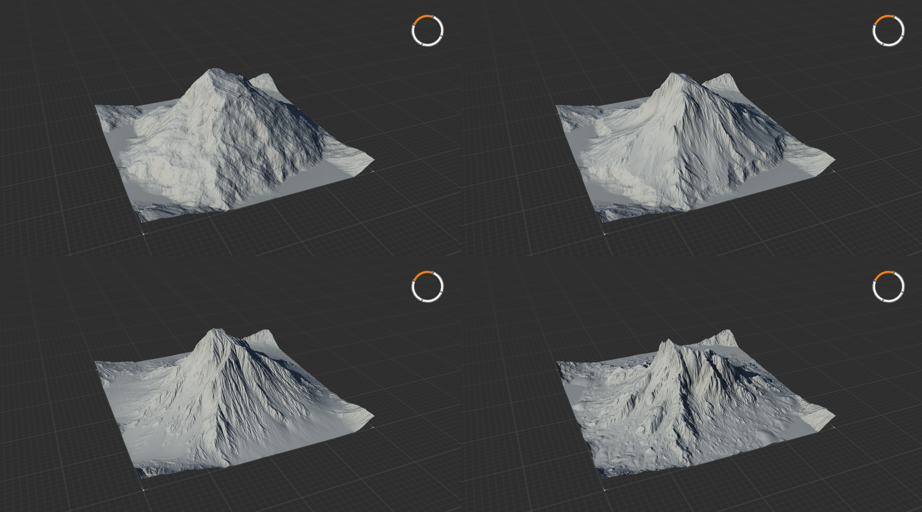
Figure 9: A mountain and three variants with progressively stronger and more aggressive erosion (
Wizard) applied. Note the formation of fine details, debris, and lots of sediment.Modifier parameters
The properties panel of all nodes contains a set of buttons at the bottom right that allow for common modifications to nodes. Several of these modifications have their own nodes with the same effect: the Clmp and Clip buttons imitate the
Clampnode, and the Blur button functions as theBlurnode.Aside from these modifications, there are two more settings that are very useful. Be pressing the '>' button, two further options appear. The Influence parameter allows you to reduce the overal effect of the node. The Drop to Floor checkbox lowers the contents of the node to the lowest possible limit, which can be very useful after combining several layers together.
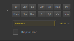
Figure 10: This panel containing modifier parameters is present on all nodes and allows for adjustments without having to add more nodes. The Drop to Floor checkbox is not visible by default and will only show up when pressing the chevron to the left of the buttons.
Using nodes as masks
Using greyscale values to create terrain
So far, we've discussed how nodes can be used to create the terrain for your map. To understand how nodes can also be used to create masks to select specific parts of the terrain, we need to quickly discuss what it is these nodes are creating.
In games such as FAF, a greyscale image creates the terrain. Every pixel of the image has a greyscale value, which ranges from 0, complete black, to 256, complete white. The value of each pixel corresponds to the height of that pixel when it is used to render the terrain. A full white pixel is at maximum height, while a black pixel is at the minimum height. Any values between 0 and 256 correspond to a height somewhere in between the minimum and the maximum.
Gaea similarly translates greyscale pixels to terrain. By default, the viewport renders the resulting 3D terrain for you, but by changing the display mode we can visualize the flat greyscale image. Right clicking on any node and select Show as, Mask, or by selecting a node and pressing
T, will change how the viewport renders that node. You will now see the greyscale pixels for your heightmap.It might be that the greyscale value is still overlaid on the 3D model, rather than shown as a flat plane. This is because Gaea always shows two layers: the node and the underlay. The underlay is the geometry that Gaea projects the contents of a node on top of. This is generally selected automatically, but similarly to how you can freeze a node into the viewport by pressing
F, a node can be chosen to serve as underlay frozen by pressingG. To visualize the greyscale image as on a flat plane, you can create aConstant, 0% heightnode and select that as underlay.If the image is dark and you would like more contrast to see the different structures, you may press the Show raw data button and the Enhanced view button on the right side of the view port (figure 11).
Since the greyscale value of each pixel is a number, we can easily make selections based on these values. The Data category of nodes contains a lot of nodes that we need to do such selections. The
Heightnode lets you make selections based on the height of the terrain, which corresponds to the higher greyscale value. Similarly,Slopeallows you to make selections of pixels that are at a certain angle, by calculating the relationship of a pixel with its neighbours.For a more extensive introduction to Data nodes to create masks, please see the Gaea tutorial on Masking.
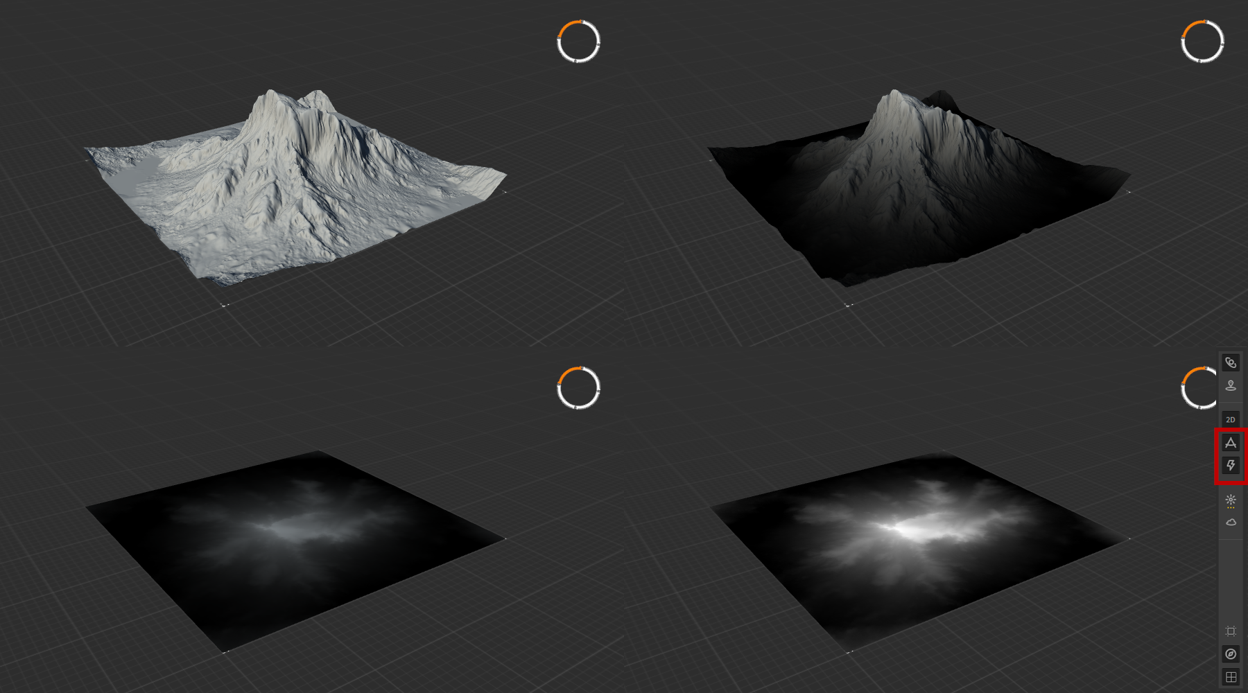
Figure 11: The 3D image, and the corresponding greyscale representation of the raw data for the heightmap. The three greyscale images show the heightmap projected on the 3D model, on a flat plane, and on a flat plane with Enhanced view enabled.
Using greyscale values to select
The greyscale values can also serve to create selections: effects of nodes can be limited to only areas that are white, and not be applied to areas that are black. Greyscale values between white and black correspond to a percentage of the effect being applied. As all nodes contain essentially nothing more than a greyscale image, the outputs of nearly all nodes can be used to make such selections.
By using masks, you get infinitely more control over how nodes are applied. One example might be limiting where erosion is applied. In the fourth panel of figure 10, the erosion is applied to the whole mountain. As an example, we will now limit the erosion to only half of the mountain.
To do this, we first set up our mountain and apply the
Wizarderosion node. Then, we create our mask. The mask that we need to limit the erosion to only half of the mountain is a mask that is half white, and half black. Only in the white regions will the erosion effect be applied. To create a full white heightmap, we could take theConstantnode and set it to 100% height. Using aTransformnode, we could then move theConstantnode halfway off of the workspace. As there is no information on the now empty half of the heightmap, these pixels will be black. The results is a heightmap that is white in one half of the image, and black on the other half. When we then use the output of thisTransformnode and chain it as the mask-input of theWizardnode, we get the result we intend (figure 12).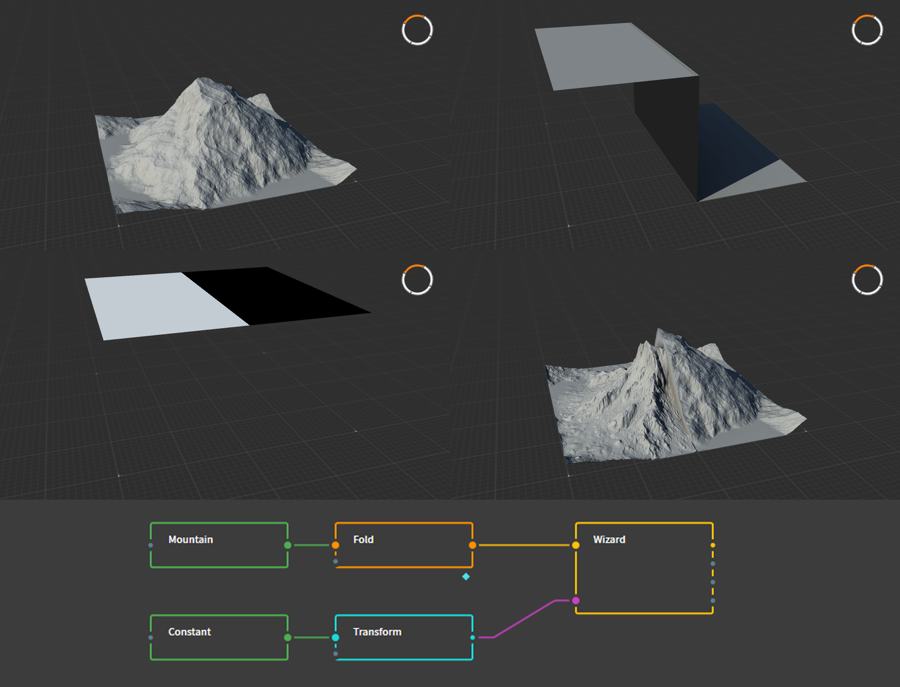
Figure 12: The erosion effect is applied to half of the mountain using a mask. Panel 2 and 3 both show the same node, but the display mode differs. The bottom panel shows the Graph to create this effect. The
Foldnode shown was used to slightly alter the result ofMountainnode, and does not affect the process of making a mask.Naturally, this specific effect is not something that would work well for a FAF map, but clearly illustrates the principle of using masks.
Other nodes
There are several other useful nodes that you might use to create more advanced materials for your map. These include the
Normal Mapnode, which can be used to create map-wide normal map decals, or theLightnode, which can be used to create map-wide shadow decals. As these nodes are more complex, they will be discussed in detail in another tutorial.Creating symmetry
As Gaea is designed to create realistic and natural terrain, it does not create symmetric terrain by default. In contrast, competitive FAF maps require symmetry to ensure no team has an advantage over the other. Luckily, by combining a few nodes we can create seamless symmetry for all kinds of terrain.
Symmetry of basic terrain
The most simple way to create a symmetric heightmap is done by using the
FlipandCombinenodes. TheFlipnode allows for three different types of mirroring: Horizontal, Vertical, and Both. By combining the flipped copy with the original, you get symmetry.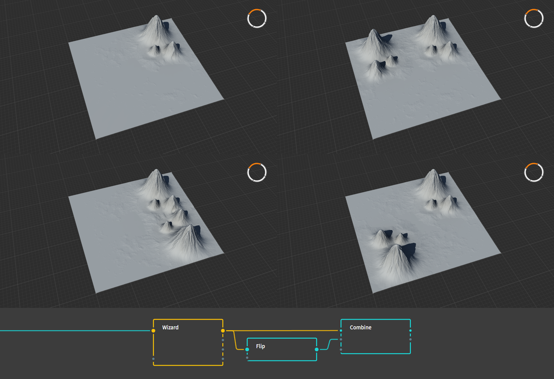
Figure 13: An example of how the
Flipnode can be used to create three different kinds of symmetry: Horizontal, Vertical, and Both.Combine, Add, 100%was used in these examples.Rendering your height mask
When you've completed your terrain, you can export it for importing into the FAF editor. To do this, take the last node in your graph and mark that node for export by selecting the node and pressing
F3, or by right clicking it and selecting Mark for Export. The marked nodes will now show up under the Build tab in the top right. Adjust the relevant settings:- Change the filetype of all masks to .raw
- Method should be left on Normal Build
- Resolution should be set to the size corresponding to your map's heightmap (257px for a 5km map, 513px for a 10km map, 1025px for a 20km map).
- Colorspace should be left on sRGB
- Range should be left on Raw, although alternatively this may be set to Remapped to rescale the whole terrain if it proves to be too tall for the FAF editor, see below.
- Baked Cache may be left on Use
After selecting where Gaea should dump the generated files, you can render the files by pressing Start Build.
Rescaling height
If, upon importing the heightmap into the FAF map editor, you realize that there is an issue with the vertical scale, you may want to adjust your heightmap. There are a few easy ways of achieving this. The
Clampnode lets you scale the whole heightmap proportionally. Connect this node to the last node of your graph and adjust as necessary. Similarly, under the modifier parameters (those little buttons at the bottom right of a node's parameter panel) you will find the Raise modifier, a circle containing an X. This parameter behaves nearly identical to theClampnode. Lastly, by setting the Range setting under the build menu to Remapped, and setting the maximum value to some fraction of 1, you can rescale the terrain.Some trial and error is likely required to find the right scale.
Common errors and checklist
If you are running into problems with importing your heightmap to the FAF editor, please check the following:
- Verify you are using the correct resolution
- Verify you exported the heightmap in the .raw file format.
- Try changing the Baked Cache setting to None and re-render.
If Gaea is producing errors and you cannot get it to work, please check the following:
- Verify that the offending node is properly connected. Remove connections and try again. Nine times out of ten you accidently connected a non-primary output to the next node that cannot use that particular type of data, or connected one node to the a secondary input of the second node.
- Force refresh the complete graph.
- Replace the bugged node.
- Restart Gaea.
If Gaea refuses to render your heightmap, attempt the following:
- Add a
Transformnode to the end of the graph, and mark that node for export. Some nodes are known not to produce an output, but theTransformnode is known to behave as expected.
Remaining questions
If you are left with questions or need help, your best bet is to check with people in the FAF discord Mapping-General channel. Alternatively, you may send me a PM on discord, or leave a message on this forum.
-
On this classified planet claimed by the Aeon Illuminate, researchers worked years on developing novel surveillance technology. The research, codenamed Project Luminary, resulted in a working prototype, the creation of the Eye of Rhianne, and later on even a minitiurized version which can be installed on the commander. Ever since, the surveillance abilities of the Aeon are without peer. // Licensed under CC BY-NC-SA 4.0. Contact the map author on FAF discord for feedback. This map is compatible with AI and is adaptive.
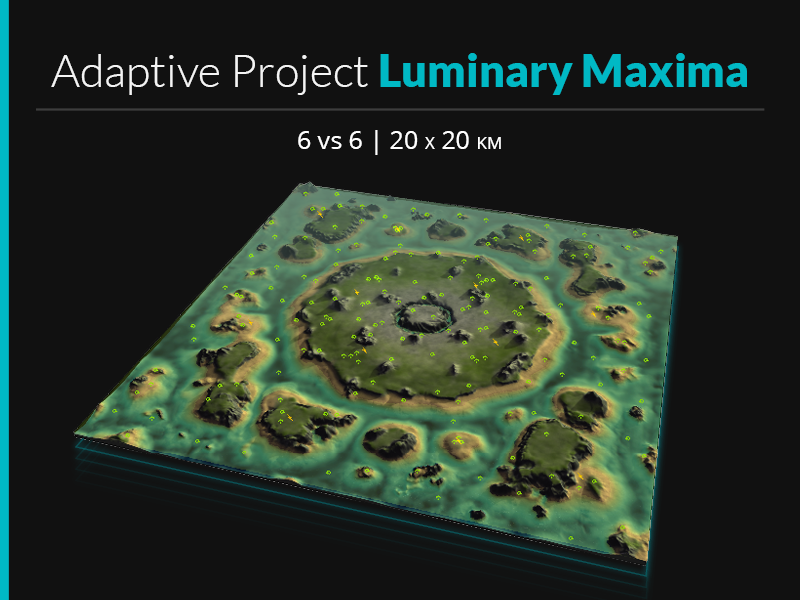
To celebrate Project Luminary winning first place in Jip's 'Princess Burke' Mapping tournament, I have released a 20km version of the map. A maximum of 12 players can play on this map, and several options are configurable: underwater mexes can be turned off, and extra hydros, core mexes, and middle mexes may be spawned in.
Due to the increased size of the map, Project Luminary Maxima is expected to be less hectic than the original, where players are likely to have to multitask navy, air, and land at the same time. Nonetheless, all three unit types will be relevant, and floating units will find lots of opportunities too.
In this 20km version, the islands that were at the edge of the map in Project Luminary have been expanded and more sea has been added. Due to the many mexes under or near water, you may expect T1 navy to be very relevant. Consider sending your commanders to the main island, to ensure that your team does not quickly lose control of the middle. Although this is a 20km map, all but one commanders spawn close enough to the center island that they will certainly be relevant by the time they arrive there.
T2 air is similarly expected to be strong on this map. It is advised not to blindly rush into T3, but rather see if there are opportunities for snipes, drops, or for supporting your navy players with torps.
The map is licensed under CC BY-NC-SA 4.0 and is compatible with AI.
-
"Under pale moon,
Across the snow
...
Did we not lose, a hundred times?
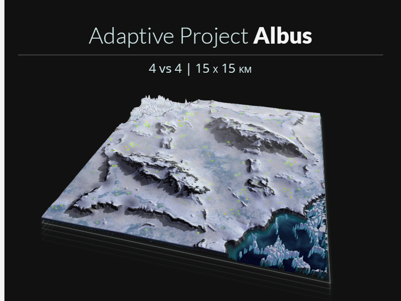
Did we not win, a hundred times?"Hello. It has been a while.
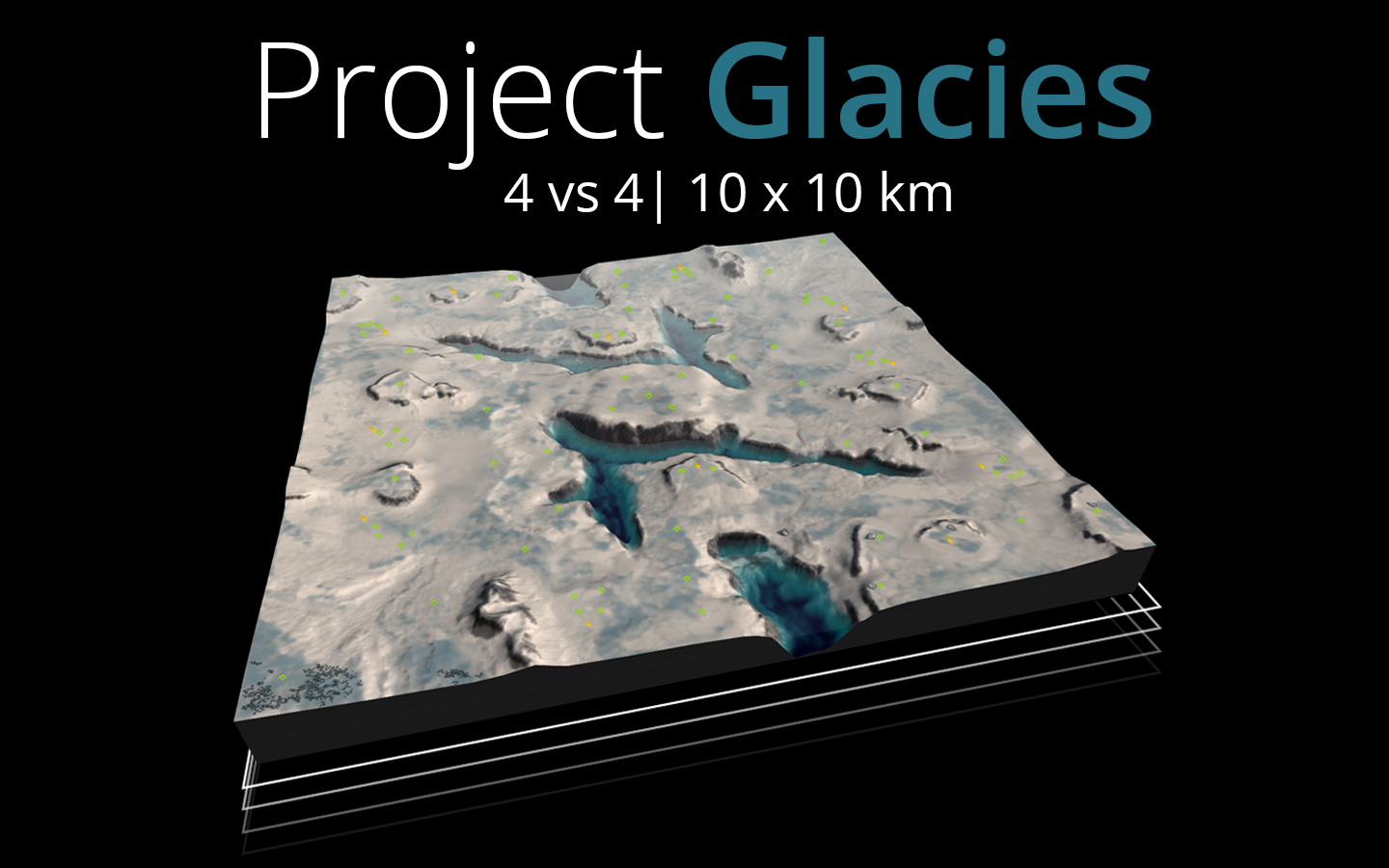
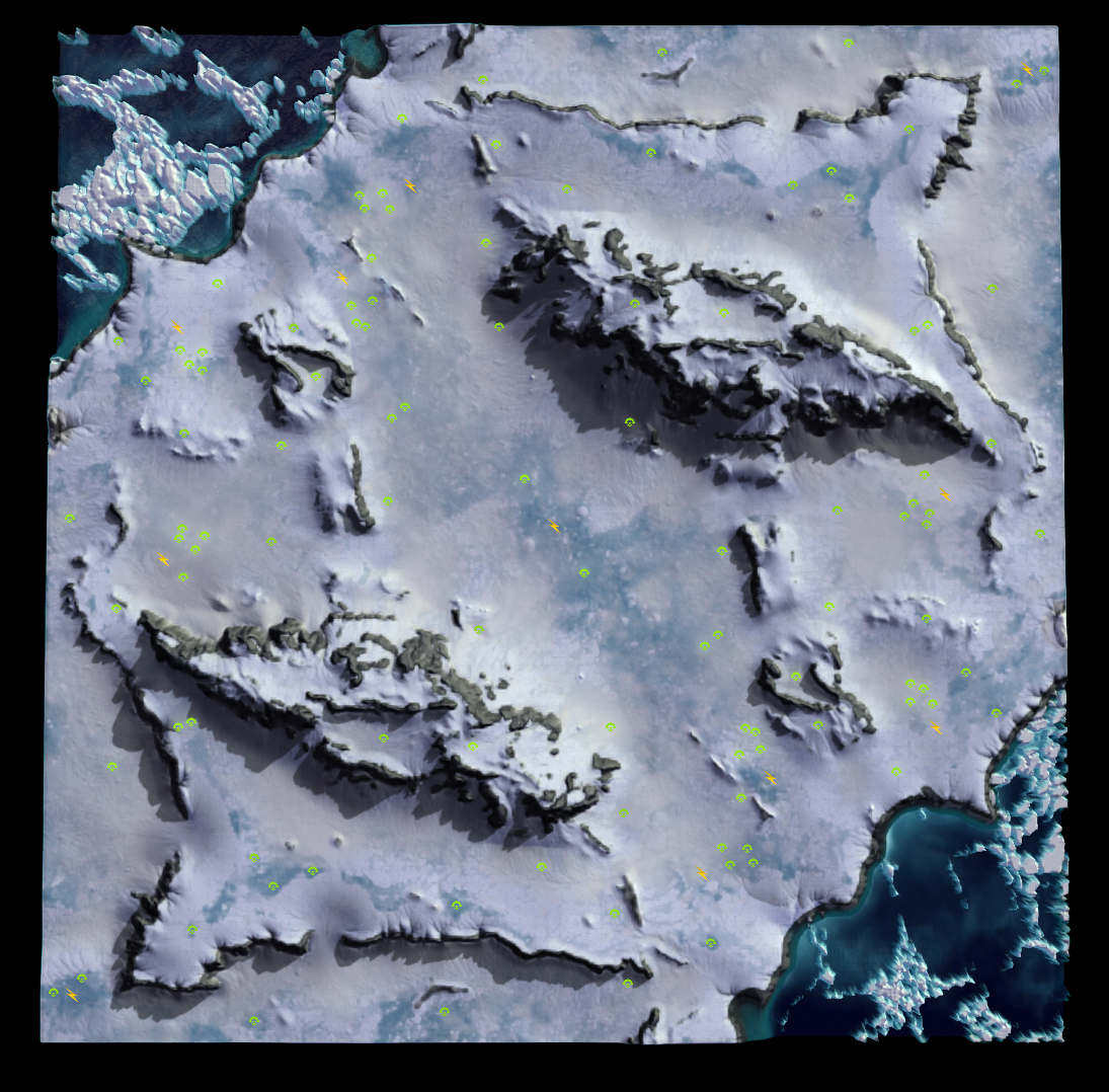
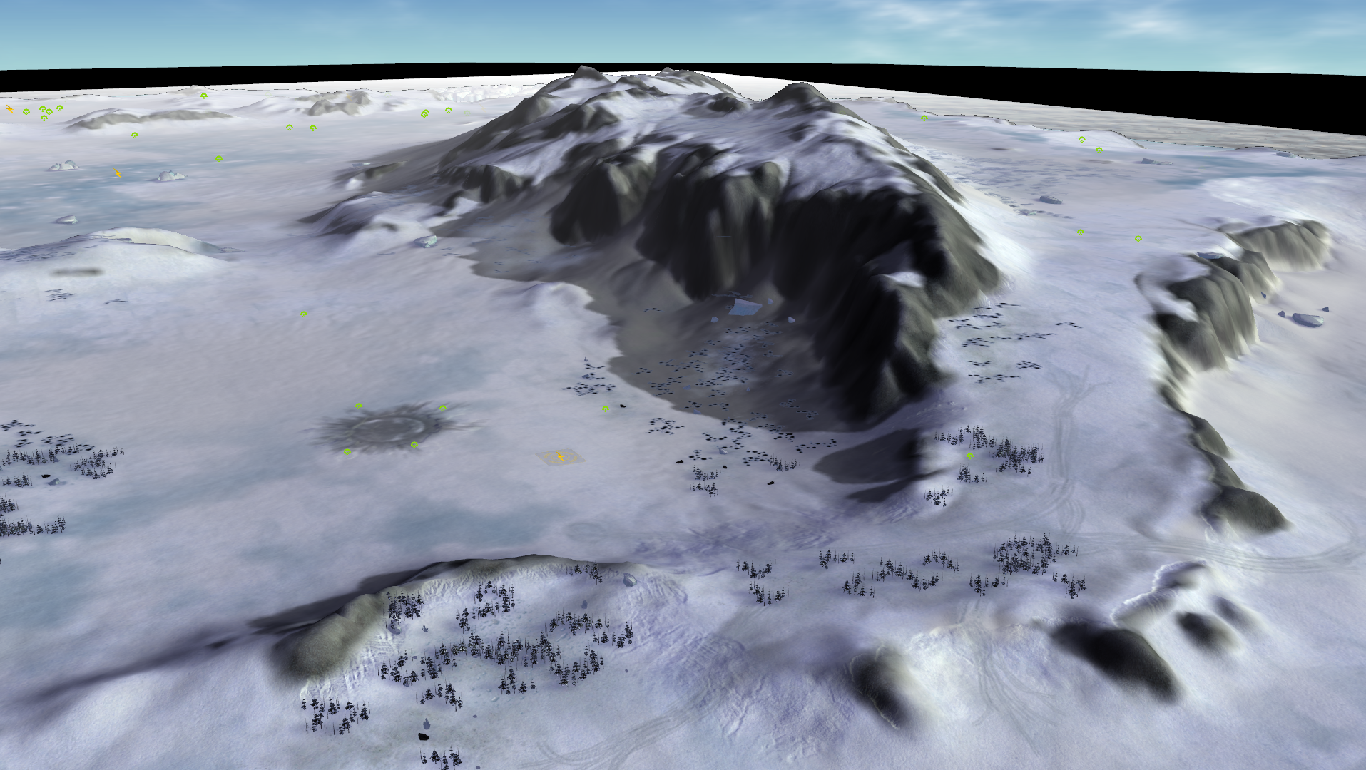
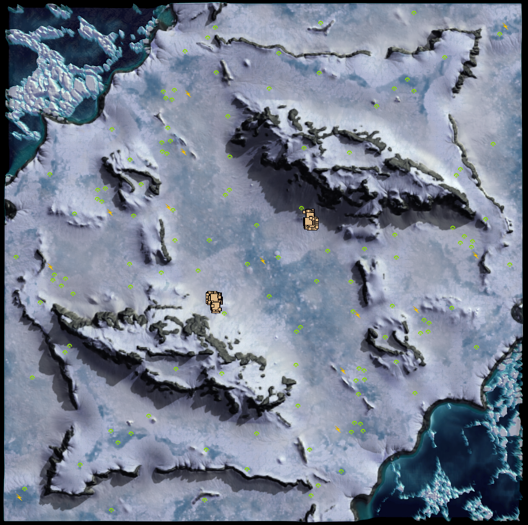
Project Albus is my first snow-type map, featuring large ice and snow covered flats. This 15x15 km map supports up to 8 players and consists of 5 lanes. The center lane is rather wide, while the lanes in the corners have several areas that serve as chokes. While the two large mountains serve as a barrier separating the main and the side lanes, the mountains can be crossed by small groups of units, albeit with some difficulty; You'll have to remain vigilant against enterprising enemies trying to raid through them.
This map was a real pleasure to create, and uses several new techniques and tricks. First and foremost is the use of asymmetry: you'll notice that the ice floe in the corner ponds are different between the two map halves. To ensure that this difference in terrain does not affect gameplay, the two ponds have been made inaccessible using terrain types. Units will not be able to access this part of the map, air units excepted.
Experiments with asymmetric texturing have worked out rather well, and textures have been applied in a more organic manner. While the main playable area has identical terrain, textures are not applied symmetrically, creating a sense of natural distribution of the snow and ice. Additionally, some experiments with creating texture masks in Gaea have led to some improvements, and I believe the quality of the masks has increased significantly compared to my previous maps.
Future iterations of Adaptive Project Albus are pending on feedback, and might lead to an adjustment of mexes and reclaim. As per usual, any feedback is welcome either in this thread, or via discord directed to Prohibitorum.
The map is licensed under CC BY-NC-SA 4.0 and is compatible with AI.
-
V3 of Project Albus has been released:
-
The map now offers support for up to 12 players (6v6). Some mexes have been added, others removed, still others moved to new locations to accomodate the new spawns.
-
Overal reclaim has been reduced by roughly 30%, as there was too much 'safe' reclaim available at the back of the bases. Total safe reclaim near each spawn is now approximately 2k per player.
-
Two small civilian outposts have been placed at the sides of the main lane and some mexes have been moved to the middle to provoke some more aggressive fighting in the main lane.
-
Some of the mountain passes have been smoothed to make sending small armies through the mountain less of a pain.
-
-
Gaea tutorial: Texturing in Gaea
A copy of this tutorial is available on the FAF wiki.
This tutorial focusses on texturing your maps with Gaea.
Using Gaea to texture your map can be used as a way to quickly experiment with different aestethics, to verify your masks are set up correctly, and as the basis for map-wide albedo decals. This tutorial will explain how to quickly design a possible map design, set up Gaea in a way that emulates how the FAF editor applies textures, and how to use this to create a textured map.
In the end, creating texture designs is a matter of taste. I normally prefer creating maps that look and feel like they are mostly natural, and make my design choices accordingly. However, given that this game of ours is about big robots fighting on alien planets, it is up to you to decide what colour and style your rocks, sand, ice, and 'grass' have. As such, in this tutorial I will try and show you the concepts behind creating these kind of map designs, rather than show you how to make any specific map designs.
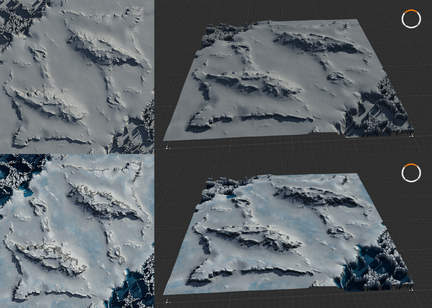
Figure 1: Example of a non-textured and textured version of my map Project Albus in Gaea.
Prerequisites
This tutorial assumes you've got a basic understanding of image editing and FAF mapping. Additionally, it is suggested you familiarize yourself with the concept of visual node based programming. A very rudimentary understanding of Gaea is also required: while I will discuss the relevant nodes and how they work, I will leave familiarizing yourself with the software for self study. Watch a few youtube tutorials on the basics, or read the general introduction to Gaea here.
Required for this tutorial is a copy of Gaea (the indie version is free to use and more than sufficient for maps up to 20km), which can be downloaded here. Additionally, an image editor such as Photoshop or Gimp is required, though the free to use online photoshop-clone Photopea works fine too. Lastly, you will need the the FAF map editor.
As with texturing in the FAF editor, applying textures to specific areas of the terrain requires masks. Creating masks in Gaea is relatively simple, but allows for high detail and complexity. As such, a seperate tutorial has been made available here.
- General introduction to GaeaOfficial documentation
- Producing terrain masks in GaeaProducing stratum masks for texturing
Terminology
In my conversations with others in the FAF discord's mapping-general channel, I've come to realize that explaining certain concepts can be a bit challenging, primarily due to the lack of clear definitions and names for some elements. To ensure that we're all on the same page, please refer to the terminology page for definitions of mapping-related terms.
In this tutorial specifically, I will be using the noun texture to mean those little tile-able images you may use in the FAF editor to cover a stratum. The verb to texture will be used to refer to everything that has to do with applying colour and textures to the terrain. When using colour-nodes in Gaea to add colour to the terrain, I will be refering to the product of those nodes as a texture design or map design. Such a map design can be used to create what other tutorials refer to as map wide albedo-decals or texture decals, the use of which is explained in a seperate tutorial.
Note that the terminology list does not include the specific names for less common terms, such as the names of elements of Gaea, as those are defined in their respective tutorials.
A review of texturing basics
In this tutorial I will introduce a workflow that aims to emulate the way that textures are applied in FAF. We will setup a graph that emulates a maximum of nine stratums, one base stratum and 8 stratums with accompanying stratum masks, stacked on top of eachother. However, the texturing in Gaea will always be an approximation of what the map will look like in the FAF editor, as the approach differs in a few critical areas. Firstly, FAF uses tiled textures: textures are repeated over the map and exposed to certain parts of the terrain using masks. Interestingly, in some way this results in both higher and lower resolution. The resolution of the textures for each pixel of the heightmap will be bigger in game: the tiled textures, especially at a low zoom-level, will result in far higher pixel density per area of the map than compared to a map-wide decal. However, since these textures are tiled, the textures aren't specific to individual pixels of the terrain heightmap, except in the sense that they are exposed to specific parts of the terrain.
Alternatively, you could texture a map using a map-wide albedo decal. Unlike tiled textures, this approach will allow you to be very specific in assign colours and texture to specific parts of the map. However, due to file size restrictions you will not be able to approach the resolution per heightmap-pixel that tiled textures will provide you. Although 16K textures might suffice for 5km maps, generally the resulting file size makes using this approach prohibitive. As a result, map-wide albedo decals should not be depended on to texture the full map without support from the tiled textures.
A better approach, to get the best of both methods, is to create a textured map in Gaea, use the result to render a map-wide albedo decall, and use that decall to support and enhance the textures applied by using the stratum layers and stratum masks. As the approach here detailed requires you to setup stratum masks anyway, using this method should not be much more effort.
Colour nodes
To texture your heightmap, there are several important nodes that you should familiarize yourself with. These nodes generally are coloured purple, designating that these nodes provide or process colour-data. Similarly, the
combinenode, which normally maintains a light blue colour to indicate it being part of the 'Adjustments' group of nodes, will turn purple when used to combine colour layers.Quick Colour
A basic node that creates colour is the
QuickColornode, which generates a gradient using two selected colours. This gradient is applied to the heightmap using the height values: the first colour is assigned to the highest part of the heightmap, and the second colour is applied to the lowest part, with all other colours of that gradient applied to the values in between these two extremes. A bias slider is available to shift the middlepoint of the gradient in either direction, letting you adjust how the gradient is applied to the heightmap. Increasing the value for Input noise will make the gradient noisy rather than smooth.Aside from using the gradient this node can produce, you may choose to select the same colour for both options, creating a single colour. When combined with the
Constantnode, this can be used to create a flat plane of one pure colour, which is a good way to approximate the result you would achieve in the FAF editor—an approach that will be discussed in detail below.CLUTer and Synth
The
CLUTernode is, in essence, an advanced version of theQuickColornode. Rather than selecting two colours to form a gradient between,CLUTerallows you to select multiple colours, and move these colours along the gradient, to create complex gradients. TheSynthnode behaves similarly, but allows you to provide an image to sample the colours from. These two nodes can be used to create more complex colour patterns, and might be used to create map-wide albedo textures.SatMap
The
SatMapsnode is similar to theCLUTerandSynthnodes, but provides complex gradients out of the box. Several hundreds of gradient presets based on satelite images are available, such as those based on mountains, deserts, and other iconic terrain. This node is a fantastic way to add a lot of colour detail to your texture, although some finetuning is often required; as these gradients were made with complex terrain in mind, the often simpler heightmaps made for FAF maps might not always produce great results out of the box.Experimenting with this node in my past projects, I've found that the best SatMaps are those with smoother gradients and fewer distinctly different colours. Additionally, by adding additional geometry to the terrain, or by using Data nodes that generate detail data masks, such as the
Texture,Soil,Rockmap, orSurfTexnodes, you usually can get better results.Combining several SatMaps, limited to specific parts of the heightmap by masks, is a great way to get a complex and well textured map quickly.
ColorFX
The
ColorFXnode serves as a way to make adjustments to colour-related nodes, in the same way that theFXnode allows you to make adjustments to heightmap greyscale values. Some colour nodes have a post-processing menu, but for those that don't this node offers all the same adjustments. This node may be used to do such things as adjust the brightness and contrast; make adjustments to the hue, saturation, and lightness (HSL); apply autolevel, equalize, or gamma adjustments; and perform adjustments that affect clarity, noise, and blur.Creating a map design
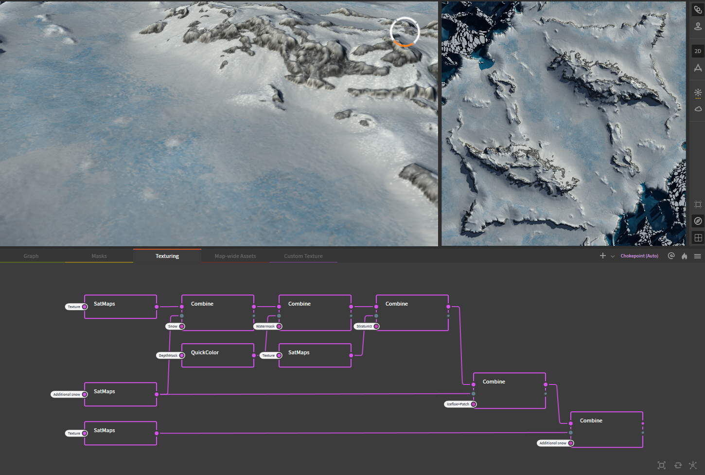
Figure 2: Overview of simple setup using SatMaps to texture the map Project Albus
Combining several different
SatMapstogether is a great way to quickly brainstorm different designs, or to make a map-wide albedo decall, without having to prepare the exact setup needed to emulate how the FAF editor would treat different stratum layers. Usually, I tend to create a map design by building different layers on top of eachother, in the same way you would see different layers of materials out in nature.As mentioned, combining several
SatMapstogether usually works rather well. Combining these is as simple as creating twoSatMapsnodes, connecting their inputs to the terrain (or such nodes asTexture,Soil, etc.) and then connecting both to theCombinenode. Generally, the mode 'Blend' works best, and the strength of the combine node may be adjusted to get the preferred effect. Using the mask-input of theCombinenode, we can guide where each of theSatMapsis exposed.Example: Map design for Project Albus
SatMaps really start to shine when combined with other SatMaps node using more complex masks. This setup does the following:
- The first
SatMapstakes the input from a Texture node, and creates a base layer of grey rock with some lighter grey highlights. - This
SatMapsis combined with one that is mostly white, which textures the first snow layer of the map using the corresponding 'snow' mask, which was prepared earlier (not shown). - A
QuickColornode is used to create a simple gradient to add in the colour for the water. Though this could be skipped, as water is added not by textures but by the dedicated water settings, but I have added the water here to give a better sense of the overal aesthetics. The mask used for thisCombinenode is derived from aSeanode (not shown). - A third
SatMapsbrings in several shades of blue to texture ice. The mask for this layer has been warped and otherwise manipulated so that the texture is not applied symmetrically, which I've found looks significantly better and does not affect gameplay. - The second
SatMapsis re-used to apply a thinner coating of snow on top of the ice. This results in a better blend between the ice and the snow, and really sells the idea of snow having fallen/been blown on top of the other terrain. - A second snow-coloured
SatMapsis used to add additional details to the terrain. The difference is difficult to see on the images above, but significant when seen in Gaea and the FAF editor.
Combined, we now have a well-textured map, one that was relatively quick to set up, which can serve as a reference when setting up the final stratum masks to texture the map in the FAF editor. To test the stratum masks, the FAF editor can be emulated within Gaea.
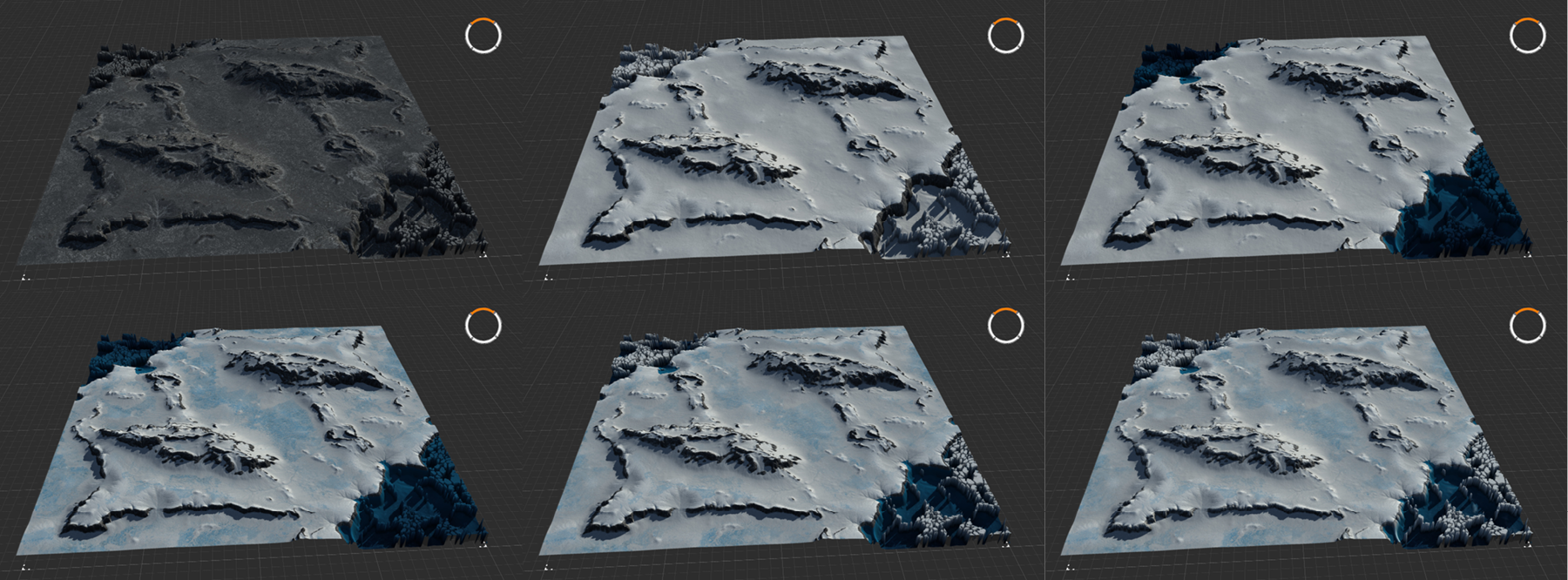
Figure 3: Result of combining SatMaps following the setup of Figure 2 using masks (set-up not shown)
Emulating the FAF editor
The FAF editor takes textures, tiles them, and then applies them to the terrain in places specified by the stratum masks. A total of 10 stratums are available although only eight will accept a stratum mask, with the remaining two stratums serving as a base and top layer. These stratums are stacked on top of eachother, with each successive stratum applying the texture on top of the previous. To emulate this approach in Gaea, we need to recreate all of these elements.
The tiled textures cannot be replicated within Gaea in the same level of detail. Instead, we can approximate the textures by creating a solid colour swatch using a
Constant, 0%and aQuickColornode. This is important, because any variation in colour should come as a result of the interpretation of the mask and the blending, not from this 'fake' texture.Eight sequential
Combine, Blend, 100%nodes emulate the eight stacked stratum layers, with each nextCombinenode using the input from the previous to add new content to. Just as how the FAF editor does not allow different stratums to blend with variable strength, the blending strength of theCombinenode should remain at 100% for all nodes. Any customization to the strength of the blending of the layers should be performed on the masks instead.As the
QuickColornodes are connected to the flat plane provided by theConstantnode, Gaea will not show the textures applied to our heightmap by default. To provide the right underlay, the last node of the heightmap graph should be pinned (by selecting the node pressingG, or by right clicking the node and selecting 'Pin as Underlay'). If you have organized your graphs over several graph tabs, you might want to create a portal from the last node of the heightmap graph, and adding a chokepoint or other placeholder node connected to that portal to allow quick selection of the terrain for underlaying.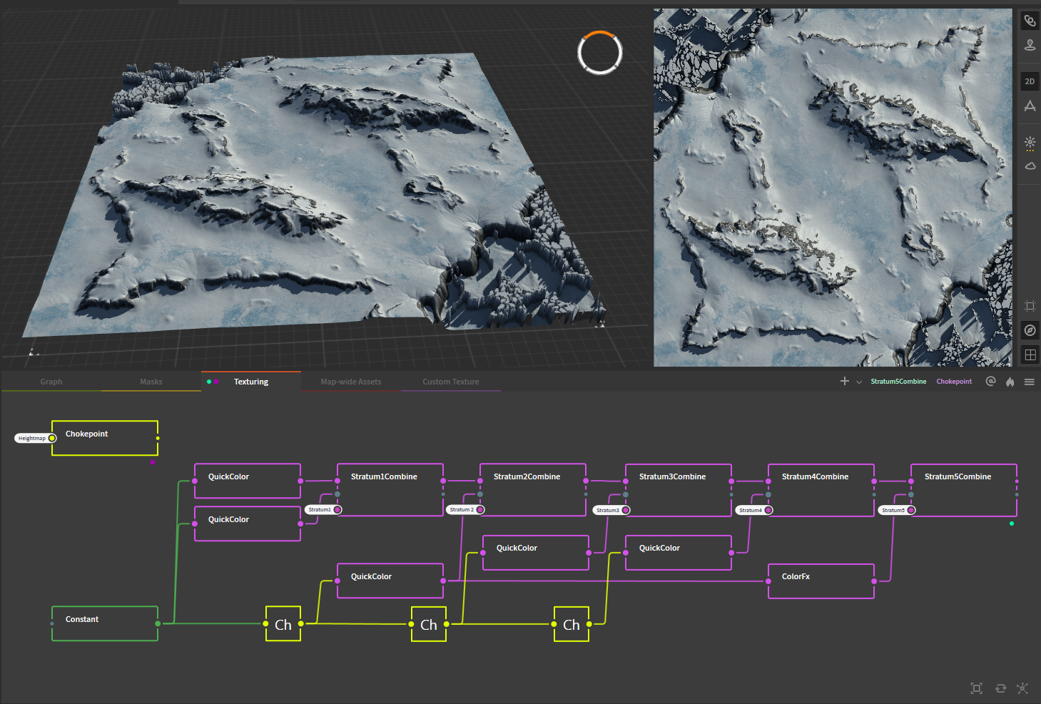
Figure 4: Emulating the FAF editor by sequentially stacking
Combinenodes and feeding themQuickColornodes and masks.With carefull tweaking of the masks and selecting the correct color in the
QuickColornode, it is possible to get very similar results as provided by theSatMapsnode based texture design. Once the design is complete, both the stratum masks and theQuickColornodes may be exported to recreate the design within the FAF editor. If theQuickColornodes are exported as well, they may be used instead of the default textures to get the most accurate recreation of the Gaea design.As these 'textures' consist of single coloured planes however, this approach will not provide you with the same level of resolution proper textures will provide.
Creating custom textures in Gaea
Thus far, we have explored how we can use Gaea to get a map design together, focussing on the larger work of texturing the map as a whole. However, we can also use Gaea to create the tileable textures that we can use in the editor to decorate the terrain with. Creating such textures in Gaea has the benefit that you can tailor your textures to your map specifically, with infinite customizability and without having to navigate any issues stemming from license restrictions.
To work well in the FAF editor, any texture we make should be tileable: repeating the texture should not result in obvious seams. Luckily, there are a few node that we can use to achieve this with little effort. Furthermore, we would like to generate a corresponding normal-map for our texture as well. In regards to the resolution of the texture, we have to keep in mind that the filesize of the texture increases significantly at higher image resolutions. Generally, 512px textures will suffice, although 1k textures are certainly possible and producing these comes at no extra effort with the way Gaea allows us to select the export resolution at any step of the process.
Example: Ice texture for Project Albus
For Project Albus I created an ice texture, matched to the shades of blue I previously selected while making the texture design. For this texture, I wanted to cracks in a sheet of ice, with some colour variation throughout the ice and some traces of snow or scuffed ice. (See figure 5 below).
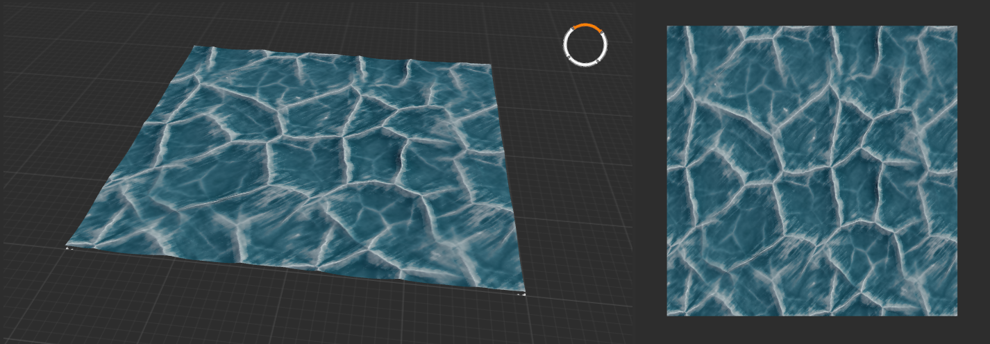
Figure 5: Custom ice texture created for Project Albus
To start, I used a combination of two
Voronoinodes at different scales: one larger for the main cracks, and one with a smaller scale to add more detailed cracks throughout. TheVoronoinode is perfect for this, as this node creates organic looking wave and crack-like patterns, and the node provides several settings that make it easy to scale or randomize the result. The two voronoi nodes used the following settings:- Main node:
Voronoi [Voronoi: Scale 82, Jitter 45, Seed 102163], [Warp: Complex, Freq 10, Amp 17, Oct 12], [Advanced Set.: ScaleX 1.0, ScaleY 1.0, Funct Euclidian, Form D], [Modifying pannel: [CLMP 0, 2]]. - Secondary node, adjustments from main node only:
Voronoi [Warp: Amp 14], [Advanced set.: ScaleX 2.0, ScaleY 2.0]
These values were the result of some experimentation, and should be considered as guidelines. Most important for this use was setting the mode to
'D', as this designates the type of algorithm the node uses to generate the noise. Different modes create very different results. Warp settings were adjusted until there was some unevenness, while maintaining the general regularity expected from ice-cracks.The two nodes were combined using a
Combine, Add, 14%node. This low blend-strength results in some of the details from the secondary node being added to the main node, but without completely overtaking the whole or making the texture too visually 'busy'.As the main terrain for this texture is now completed, the output of this node is used to create a normal-map using the
Normal Mapnode. Designing the colours for this texture is, again, the result of experimenting with, and continued adjustments of, different settings. In general however:- Several 'Data' nodes were used as the inputs for the
QuickColourandSatMapsnodes. These include theTexture,Soil, andSurfTexnodes. The goal of these nodes is to provide more colour variation and noise than what would result from connecting the colour nodes directly to the heightmap. - Several stages of
QuickColornodes with slightly different inputs and colour settings are blended together, to get more complex variation in colour. - White highlights are added using the
SurfTexnodes.
To ensure that the texture was seamlessly tileable, the two voronoi nodes were, initially, individually attached to a
Seamlessnode, which adjusts the edges of the texture to ensures that it will be able to be tiled seamlessly. Later tests in the editor showed that adding aSeamlessnode before colourizing the texture would result in a visible line regardless of the now seamless terrain. To resolve this issue,Seamlessnodes were added after the texture was colourized. AsSeamlessnodes will not accept the 3-channel colour outputs provided by colour nodes, anRGBSplitnode was used to seperate the 3-channel input into 3 1-channel outputs, which were individually connected to aSeamlessnode before merged back into 1 3-channel output using theRGBMixnode, which resolved the issue. Similarly, aSeamlessnode was added between theCombinenode containing the completed terrain and theNormal Mapnode that was previously connected directly. The settings of all theSeamlessnodes were, naturally, identical.Final colour corrections were made using the
ColorFXnode, including adjustments to brightness and contrast, HSL, and autolevel. Lighter and darker versions of this texture were similarly created using additionalColorFXnodes, adjusting the brightness and contrast, as well as the HSL as necessary.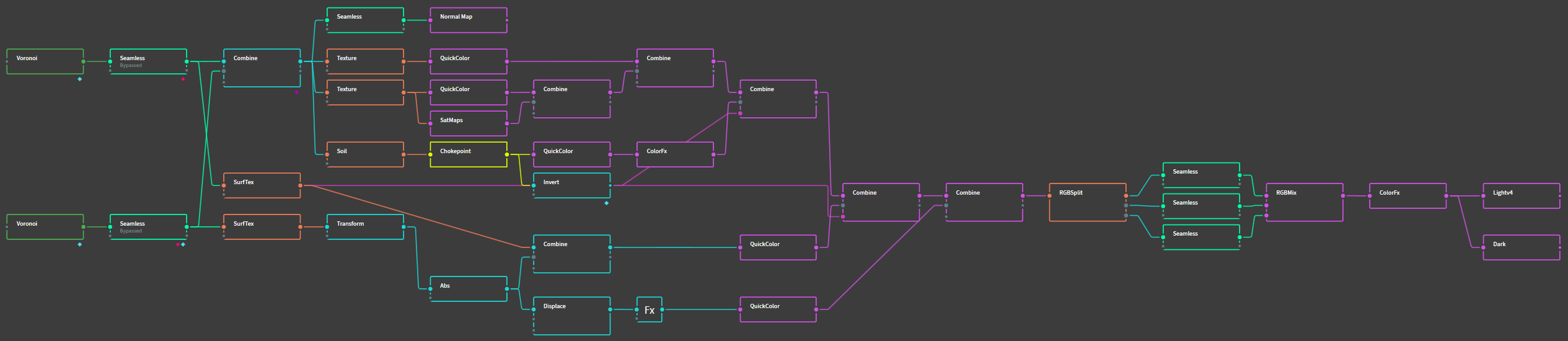
Figure 6: The complete graph for the Ice texture. Note that the two
Seamlessnodes connected to theVoronoinodes are bypassed, which de-activates their effects. These two nodes were left in the graph to support the above explanation on the use of theSeamlessnodes.Remaining questions
This tutorial should provide you with all the basic knowledge needed to start making your own map design and custom textures. However, if you are left with questions or need help, your best bet is to check with people in the FAF discord Mapping-General channel. Alternatively, you may send me (IndexLibrorum, or Prohibitorum) a PM on discord, or leave a message on the forum.
-
V7 of Project Albus has been released:
-
After playtesting the map, some mexes have been added, others removed, still others moved to new locations to better balance the slots.
-
Reclaim has been slightly rebalanced.
-
The blinking 'beacon' type building was removed from the civilian bases, because it was very distracting.
-
Some changes to decals and texturing should make the terrain, including the mountain passes, easier to read.
-
Project Albus has been submitted for review for the matchmaker pool.
-
-
God, these maps all look amazing.
Can't wait to play them! Maybe i'll even become a mapper myself; seeing this sure does motivate me. -
Hi Index, I wanted to give Gaea a test run to export one of my height maps and tweak the terrain a bit then import it back into the Map Editor. Problem I ran into is, I was able to create different nodes in GAEA and got my heightmap looking the way I wanted it with 3 different nodes, but when I tried to mark for export and Build them, nothing appears in the folder I created to export them....what could I be doing wrong? a quick window pops up that looks like a DOS screen when I hit the build button, but nothing gets created in the folder I created to Build it/Export it to
-
ok got it working now to save the nodes to files...however now when I try to import new GAEA modified heightmap back into a my Map editor its says wrong file size
-
ok i think i got it....when you build the nodes you have to select the proper resolution of the map size +1 for it to import properly as a height map in the editor.....thanks for your help
-
 A Askaholic referenced this topic on
-
@oncehandsome Yea, you got to mark a node for export, and then set the filetype and resolution that you need. I'll see if I can make sure that information is clearly explained in the tutorials.
I don't consistently keep an eye on the forum, so if you have questions for me or need help w/ Gaea your best bet is to send me a message on discord.
@Inspexor Glad you like 'em! Definitely give mapping a try. We've got loads of resources to help you get started, and a decently sized group of people who are more than willing to give you a hand. Add me on discord if you wanna have a chat about Gaea or have questions etc.
-
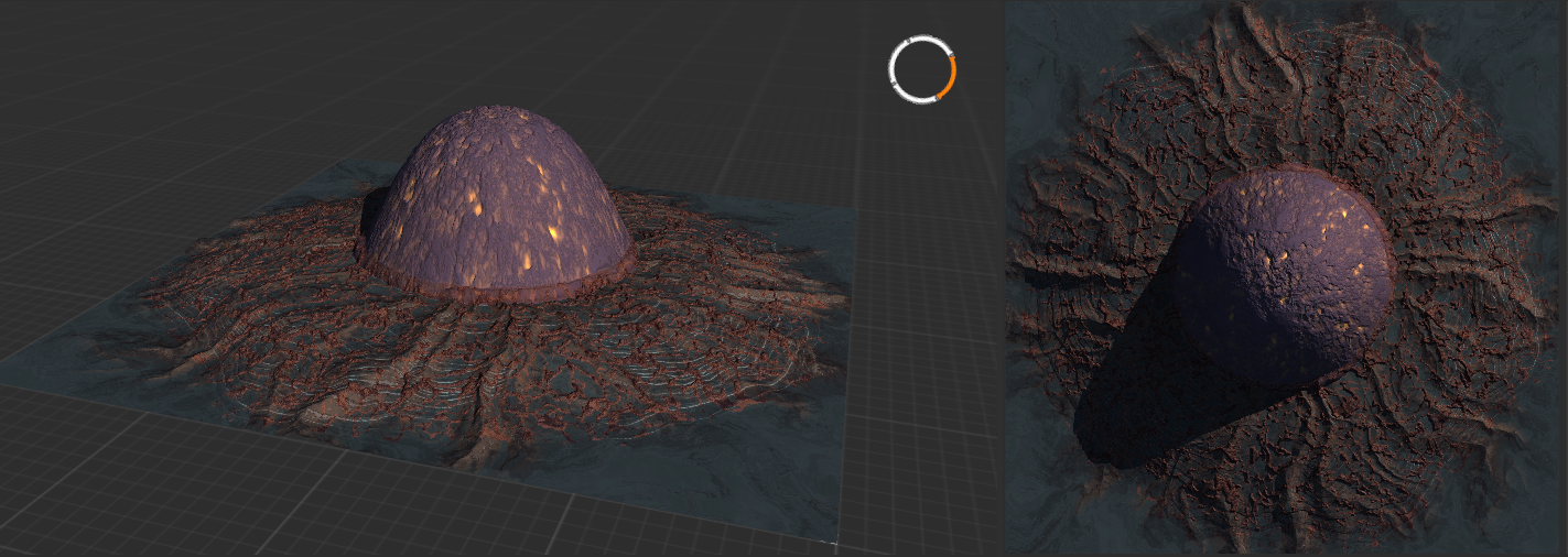
This once lush and verdant garden world hosted a classified UEF research facility, researching the first components of the Black Sun doomsday device. We do not know what happened, but all that is left now is a crater and the scattered remnants of the research complex, the planet razed to the ground. // CC BY-NC-SA 4.0. AI compatible.
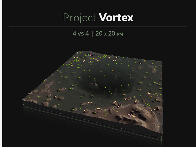
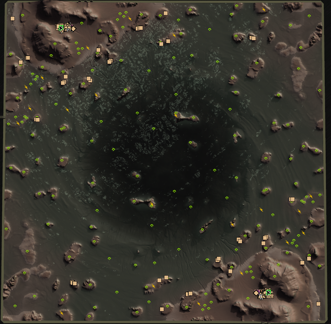
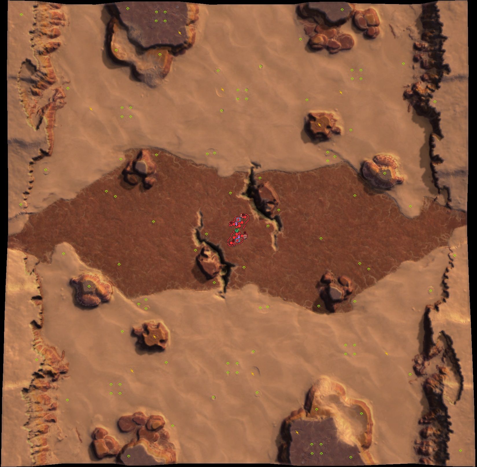
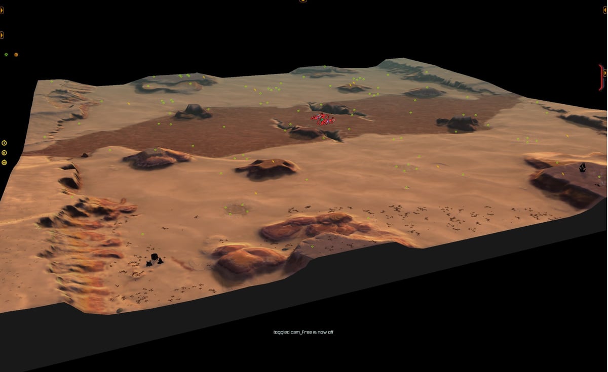
For the 'Brigadier Fletcher' tournament I submit Project Vortex. The map was designed as a all-out navy brawl: every bit of terrain gained will come with another mex for you to claim. Small islands, many with mexes and/or chunks of reclaim are scattered across the map. Most of these islands are low enough that frigates will be able to shoot over them, although some larger ones have some cliffs and mountains.
The spawns are located on the top left and bottom right corners, with two players starting in the water. To start off, these water spawns get two hydros, but will then have to find dry land to expand their powergrid and build non-navy factories. The remaining corners provide some more reclaim, as well as larger islands that allow for some very aggressive forward factories.
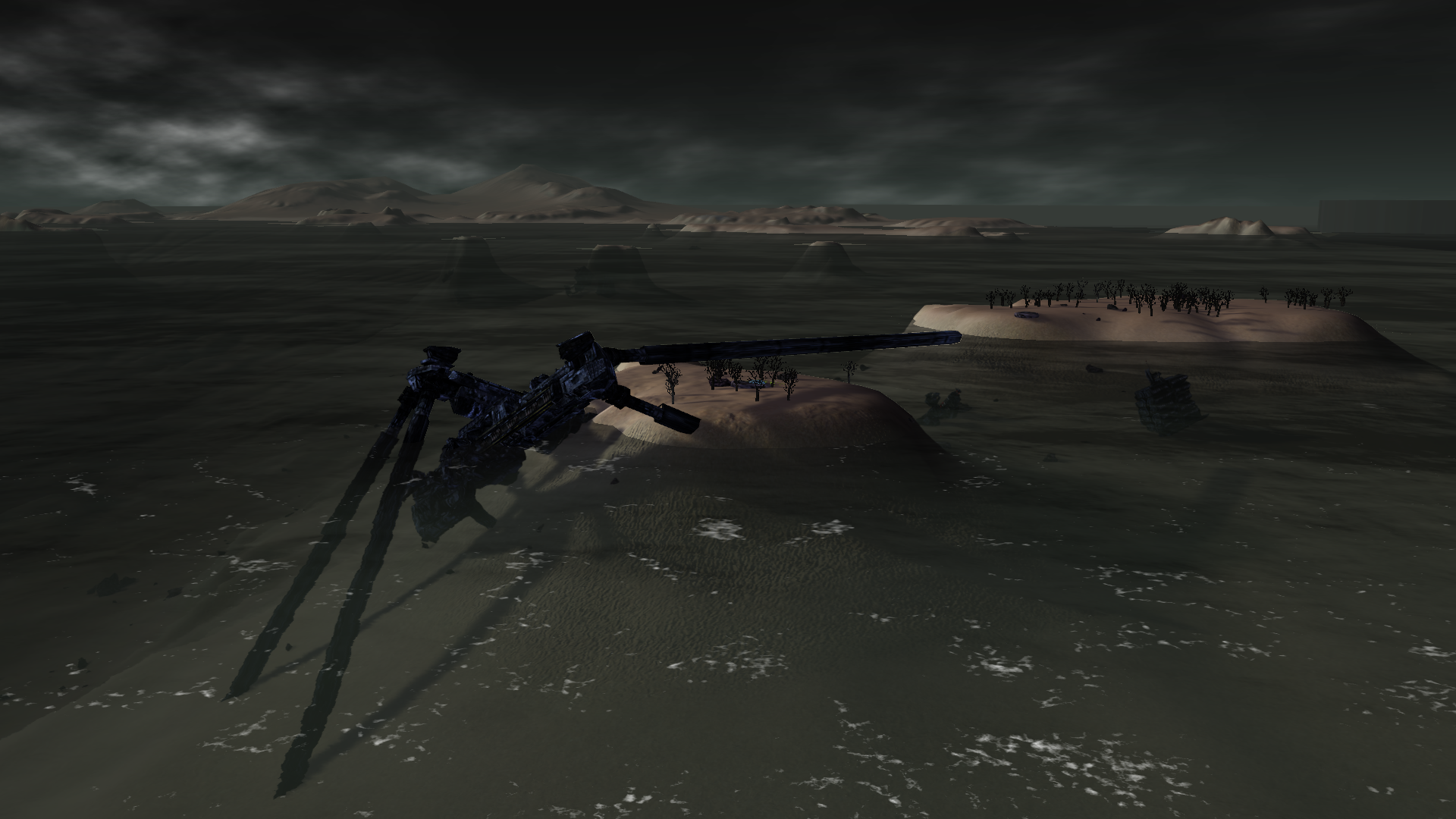
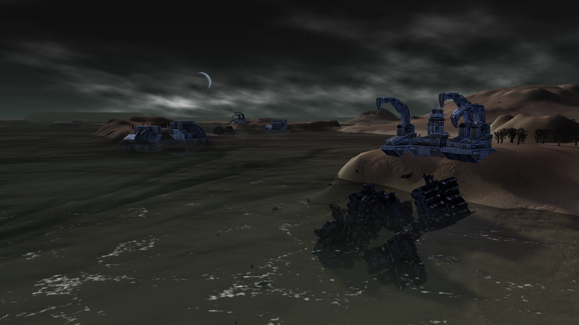
Thematically, this map shows the result of a scientific disaster: all that remains of the research facility that was once present on this planet is a large crater in the center. What survived of the buildings from the research complex was blasted outwards, and later moved around by the water that ended up filling the crater. The effects on the region as a whole was disastrous: no life remains. Only the charred husks of what were once large forests teeming with life provide an indication that this was once a verdant garden world. Across the map you'll find many buildings that have since gotten stuck or washed ashore of the many islands. Some newer structures include UEF cranes and a civilian base, indicating that the UEF has started salvaging efforts.
The center of the crater remains a danger to this day, and it is not recommended that commanders are dropped into the deep.
"Design is an iterative process. The required number of iterations is one more than the number you have currently done. This is true at any point in time."
See all my projects:

-
Something that might feature in a future map... ALIEN EGG.
-
Does it hatch?
-
@indexlibrorum said in Index Librorum's Maps, assorted projects, and Gaea tutorials:
The center of the crater remains a danger to this day, and it is not recommended that commanders are dropped into the deep.
...what happens if you do??
-
@deletethis
...what happens if you do??
I will leave figuring that out as an exercise to the reader
")
Alternatively, a relevant quote from one of my favorite books:“And so the First Under the Night came across a portal where great danger might lurk, and upon witnessing it halted and sought the council of Sve Noc. ‘O Night,’ said the First, ‘what wisdom do you offer?’ And so the Young Night answered thus: ‘Try a foot first.'”
– Extract from the ‘Parables of the Lost and Found’, disputed Firstborn religious textDoes it hatch?
Just a terrain piece! Be glad for it, I doubt whatever would be in an egg like that would be friendly.
-
Several interesting updates!
Project Mesa HD
Project Mesa was the first map I ever made. It was also the first project I made in Gaea. Consequently, on both the map-making side and the Gaea side there was a lot of room for improvement.
So improvements were made! Released under the new name 'Project Mesa HD', the new map features several fixes to the terrain (which mostly focus on flattening and scaling the map to solve height-related issues), some changes to the mex layout, better reclaim, and much improved use of decals. Pictures at the end of the post.
I have one or two areas left that I can work on to further improve the visuals of this map and may update again in the future, but for now you can find Project Mesa HD in the mapping vault and in this month's 4v4 matchmaking queue.
A github repository for project Mesa assets and project files
I have released a github repository which contains a growing set of decals and textures related to the Project Mesa HD map. The textures and decals will soon become part of the main FAF repository, and thus become available for everyone to use through the FAF editor.
Along with these new mapping assets, I have included the Gaea project files that were used to create the map and assets. If you're interested in working with Gaea, you may want to have a look at how I've created this map and the decals.
Hello! It looks like you're interested in this conversation, but you don't have an account yet.
Getting fed up of having to scroll through the same posts each visit? When you register for an account, you'll always come back to exactly where you were before, and choose to be notified of new replies (either via email, or push notification). You'll also be able to save bookmarks and upvote posts to show your appreciation to other community members.
With your input, this post could be even better 💗
Register Login